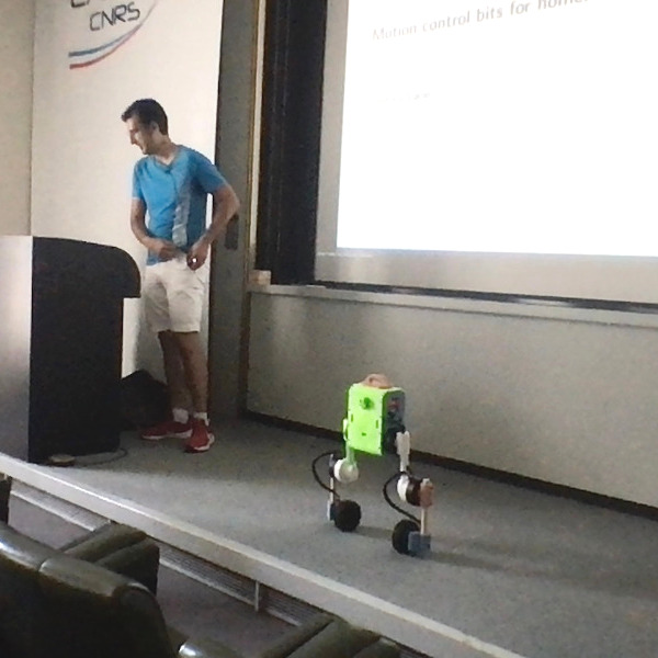
Motion control bits for homemade robots

Talk given at LAAS-CNRS on 19 July 2022.

Abstract

Picture from the presentation with Upkie onstage

We have learned a lot from big expensive robots, but their weight and price are likely damping further progress. In this talk, we will follow an alternative made possible by recent innovations in actuators: light homemade robots, of the kind that can bump, fall on, or be lifted by us with no harm. By aiming for less actuators and lower complexity, we end up with morphologies that don't fit exactly the bill of previous ideas. This is a good start to revisit them! We will tour some examples from the open source software and hardware of Upkie, a wheeled biped robot that proudly stands on 3D printed parts and sawed broomsticks (among other mechanical marvels).

Content

pdf Slides
youtube Recording (42 min)
github Motion control software for Upkie
youtube James Bruton, great explorator of new morphologies

Transcript

The following transcript was initially generated by:

vosk-transcriber -n vosk-model-en-us-0.22 -i audio.wav -o transcript.txt

Thank you everybody, I'm thrilled to be here. Thank you for your warm welcome and allowing me to speak today. This is going to be kind of an informal introduction. It should be really low level and chill, so I hope you enjoy, and don't hesitate to stop anytime if you have questions. [You can also join the discussion by posting a comment below.]

Today I would like to tell you about motion control, well motion control in particular because these are questions I'm very fond of, but also homemade robots in general, and what we can do with them.

Short bios are never short enough

So that [first slide]'s more for a quick background, as I've been working in teams on the following robots. Three years ago with HRP-4, we had a project of showing that you could take a humanoid inside an aircraft factory and that it could move around, locate itself, or do useful things like climbing stairs and crossing challenging parts in the environment. This was a research project, and after it was over I went to a company who was interested in pretty similar use cases. With quadrupeds, but similar use cases, and in terms of how we do motion control also, similar ideas from the state of the art that I assume you're already familiar with, like whole body control, torque control or position control, this kind of things.

It was also a great experience and I really liked ANYbotics as a company. After my time working with them I took some time off, did a whole bunch of things that we can talk about at a personal level, and one of them was a personal project which you see here [pointing to Upkie on stage] (which interestingly has started drifting to the side, usually [this controller] drifts more forward). This is Upkie, a wheeled biped made at home with whatever you can get your hands on through online retail, and learning a bunch of stuff, very basic, like 3D printing or [basic] electronics.

Before we talk about Upkie in particular, I would like to make a first point about morphology, or the morphology of robots, and how it has influenced the kind of techniques that we develop.

Blast from six years ago

If we look at basically six years ago (I'm a bit cheeky I'm showing you a Korean robot because I assume everybody here already knows the Japanese robots) we had basically two ways to do robots and implement locomotion on them. They were mostly bipeds and we would go either for position control with extra force sensing, or as famously shown by Boston Dynamics go for hydraulics and torque control. These choices were coupled at the time but there's not really a need for that, so if we look at joint control, I mentioned either position control or torque control, we want to look at the joints but also at what kind of sensing you have because it's always about control and observation.

Position versus torque control

With position controlled robots we would add force sensors, because we lost the backdrivability through the geartrains, and with torque controlled robots we could also sense joint torques, so [control and observation] were coupled and that was convenient. If you sense forces through joint torques you have a bit more work to do in state observation so, here [slide 3] it's heavier in terms of the theory, or in terms of the code you're going to implement, it's lighter if you have directly a force sensor because you can just start by trusting it and then move from there.

Whole-body impedance versus admittance control

And then about whole body control, so you know how you regulate all your tasks at the same time and your interactions with the environment, there is a very standard way of computing torques by solving an optimization problem, which I would say is whole-body impedance control, in the sense that you are sending directly forces and then you have position tasks to manage. Or you could do whole-body admittance control for position controlled robots where you're controlling your joints in position and you control forces only where you have a force sensor, so at the feet for big bipeds.

I don't know about you, but for me, six years ago our technology really looked like this, there were two avenues and [it felt like] either you go here or there. So it was a bit, let's say polarized.

Here come the wheels

Hopefully, I mean thankfully (I'm very fond of it), wheels came in! And again Boston Dynamics showed the way, but now we're starting to see increasingly more and more wheels, and I want to make the point that wheels are really fun in the sense that they don't fit exactly the bill of what we had been doing before, when we were saying "oh we have a force at the end effector, we want to control the force there, that's the story", because with wheels you're still going to get the same story but you'll start to see also [that] it's not the complete picture, you're not just controlling the force. Sometimes you're rolling your wheel because you want to control the position of your contact points, but [doing so is] also exerting a [ground tangential reaction] force on you, so there are a whole bunch of interesting things with wheels.

Exploring degrees of freedom

And not only wheels, but also in the number of degrees of freedoms of robots. Handle is kind of a big thing, you have the legs, you have the counterweight, you have an an arm on it. You could take a regular quadrupled and add wheels [to it], so then you get to sixteen degrees of freedom, a bit more complexity there, or you can go the other way around and try to trim the number of degrees of freedom to the minimum, and you get something like Ascento which has four degrees of freedom, controlled at least, and then you have this extra spring in the knee which brings you some extra behavior. So what I think is really cool about this is that we get to have new entries in this table, and actually it starts to look more like a technological tree where we are branching, and, you know, there are not just two ways but there are actually many ways we could explore.

New feature space coordinates

If you're interested [we can continue the comparison table], so here I added Ascento [to the table]: we still have torque control, and for sensing and you also sense joint torques and your usual IMU, but state observation is a bit of a middle-ground: it's not as simple as with, let's say, an HRP robot and just looking at the force sensors, there is a bit of dirty work, but it's also not as heavy as having a whole body state estimator with the whole [set of] equations of motions, all your constraints, etc. So it stands somewhere in between, and I think this is really cool, this is a sign that we can play with ideas and test them against new architectures, new morphologies.

Building our own

Okay, so that was a one point, new morphologies are coming. My second point today will be, well, they are coming because also we can build our own robots, and we can try stuff directly. This has become easier.

One big reason why this has become easier, it's not the only one but one big reason is about the availability of actuators. The market for us has become better recently: you don't have to go to a research lab anymore to build some handcrafted actuators, you can go to websites today and order actuators that are delivered to your door. That simplifies a whole lot of things, not only for people working from home but also for research in general, because it simplifies the process a lot. You don't have to get a quote, and perhaps approval from a [hierarchy] of people involved [on both sides], if you have access to a credit card, you can order directly.

Quasi direct drive actuators

There are two main kinds of actuators on the market today. First, Ben Katz's design which came with the Mini Cheetah, the quasi direct drive actuators. These are the ones that you can also see running on Upkie right now. They are commercially available [for instance from mjbots], which is really convenient. They have a torque range which is very decent, they can hold several Newton-metres continuously, and this particular actuator at 6 N.m\def\bfA{\boldsymbol{A}} \def\bfB{\boldsymbol{B}} \def\bfC{\boldsymbol{C}} \def\bfD{\boldsymbol{D}} \def\bfE{\boldsymbol{E}} \def\bfF{\boldsymbol{F}} \def\bfG{\boldsymbol{G}} \def\bfH{\boldsymbol{H}} \def\bfI{\boldsymbol{I}} \def\bfJ{\boldsymbol{J}} \def\bfK{\boldsymbol{K}} \def\bfL{\boldsymbol{L}} \def\bfM{\boldsymbol{M}} \def\bfN{\boldsymbol{N}} \def\bfO{\boldsymbol{O}} \def\bfP{\boldsymbol{P}} \def\bfQ{\boldsymbol{Q}} \def\bfR{\boldsymbol{R}} \def\bfS{\boldsymbol{S}} \def\bfT{\boldsymbol{T}} \def\bfU{\boldsymbol{U}} \def\bfV{\boldsymbol{V}} \def\bfW{\boldsymbol{W}} \def\bfX{\boldsymbol{X}} \def\bfY{\boldsymbol{Y}} \def\bfZ{\boldsymbol{Z}} \def\bfalpha{\boldsymbol{\alpha}} \def\bfa{\boldsymbol{a}} \def\bfbeta{\boldsymbol{\beta}} \def\bfb{\boldsymbol{b}} \def\bfcd{\dot{\bfc}} \def\bfchi{\boldsymbol{\chi}} \def\bfc{\boldsymbol{c}} \def\bfd{\boldsymbol{d}} \def\bfe{\boldsymbol{e}} \def\bff{\boldsymbol{f}} \def\bfgamma{\boldsymbol{\gamma}} \def\bfg{\boldsymbol{g}} \def\bfh{\boldsymbol{h}} \def\bfi{\boldsymbol{i}} \def\bfj{\boldsymbol{j}} \def\bfk{\boldsymbol{k}} \def\bflambda{\boldsymbol{\lambda}} \def\bfl{\boldsymbol{l}} \def\bfm{\boldsymbol{m}} \def\bfn{\boldsymbol{n}} \def\bfomega{\boldsymbol{\omega}} \def\bfone{\boldsymbol{1}} \def\bfo{\boldsymbol{o}} \def\bfpdd{\ddot{\bfp}} \def\bfpd{\dot{\bfp}} \def\bfphi{\boldsymbol{\phi}} \def\bfp{\boldsymbol{p}} \def\bfq{\boldsymbol{q}} \def\bfr{\boldsymbol{r}} \def\bfsigma{\boldsymbol{\sigma}} \def\bfs{\boldsymbol{s}} \def\bftau{\boldsymbol{\tau}} \def\bftheta{\boldsymbol{\theta}} \def\bft{\boldsymbol{t}} \def\bfu{\boldsymbol{u}} \def\bfv{\boldsymbol{v}} \def\bfw{\boldsymbol{w}} \def\bfxi{\boldsymbol{\xi}} \def\bfx{\boldsymbol{x}} \def\bfy{\boldsymbol{y}} \def\bfzero{\boldsymbol{0}} \def\bfz{\boldsymbol{z}} \def\defeq{\stackrel{\mathrm{def}}{=}} \def\p{\boldsymbol{p}} \def\qdd{\ddot{\bfq}} \def\qd{\dot{\bfq}} \def\q{\boldsymbol{q}} \def\xd{\dot{x}} \def\yd{\dot{y}} \def\zd{\dot{z}} 6~\mathrm{N.m} I think it can hold for about five minutes, so you can have some decent motions; not too fast, you don't have to use just peak. Peak torque is about 16 N.m\def\bfA{\boldsymbol{A}} \def\bfB{\boldsymbol{B}} \def\bfC{\boldsymbol{C}} \def\bfD{\boldsymbol{D}} \def\bfE{\boldsymbol{E}} \def\bfF{\boldsymbol{F}} \def\bfG{\boldsymbol{G}} \def\bfH{\boldsymbol{H}} \def\bfI{\boldsymbol{I}} \def\bfJ{\boldsymbol{J}} \def\bfK{\boldsymbol{K}} \def\bfL{\boldsymbol{L}} \def\bfM{\boldsymbol{M}} \def\bfN{\boldsymbol{N}} \def\bfO{\boldsymbol{O}} \def\bfP{\boldsymbol{P}} \def\bfQ{\boldsymbol{Q}} \def\bfR{\boldsymbol{R}} \def\bfS{\boldsymbol{S}} \def\bfT{\boldsymbol{T}} \def\bfU{\boldsymbol{U}} \def\bfV{\boldsymbol{V}} \def\bfW{\boldsymbol{W}} \def\bfX{\boldsymbol{X}} \def\bfY{\boldsymbol{Y}} \def\bfZ{\boldsymbol{Z}} \def\bfalpha{\boldsymbol{\alpha}} \def\bfa{\boldsymbol{a}} \def\bfbeta{\boldsymbol{\beta}} \def\bfb{\boldsymbol{b}} \def\bfcd{\dot{\bfc}} \def\bfchi{\boldsymbol{\chi}} \def\bfc{\boldsymbol{c}} \def\bfd{\boldsymbol{d}} \def\bfe{\boldsymbol{e}} \def\bff{\boldsymbol{f}} \def\bfgamma{\boldsymbol{\gamma}} \def\bfg{\boldsymbol{g}} \def\bfh{\boldsymbol{h}} \def\bfi{\boldsymbol{i}} \def\bfj{\boldsymbol{j}} \def\bfk{\boldsymbol{k}} \def\bflambda{\boldsymbol{\lambda}} \def\bfl{\boldsymbol{l}} \def\bfm{\boldsymbol{m}} \def\bfn{\boldsymbol{n}} \def\bfomega{\boldsymbol{\omega}} \def\bfone{\boldsymbol{1}} \def\bfo{\boldsymbol{o}} \def\bfpdd{\ddot{\bfp}} \def\bfpd{\dot{\bfp}} \def\bfphi{\boldsymbol{\phi}} \def\bfp{\boldsymbol{p}} \def\bfq{\boldsymbol{q}} \def\bfr{\boldsymbol{r}} \def\bfsigma{\boldsymbol{\sigma}} \def\bfs{\boldsymbol{s}} \def\bftau{\boldsymbol{\tau}} \def\bftheta{\boldsymbol{\theta}} \def\bft{\boldsymbol{t}} \def\bfu{\boldsymbol{u}} \def\bfv{\boldsymbol{v}} \def\bfw{\boldsymbol{w}} \def\bfxi{\boldsymbol{\xi}} \def\bfx{\boldsymbol{x}} \def\bfy{\boldsymbol{y}} \def\bfzero{\boldsymbol{0}} \def\bfz{\boldsymbol{z}} \def\defeq{\stackrel{\mathrm{def}}{=}} \def\p{\boldsymbol{p}} \def\qdd{\ddot{\bfq}} \def\qd{\dot{\bfq}} \def\q{\boldsymbol{q}} \def\xd{\dot{x}} \def\yd{\dot{y}} \def\zd{\dot{z}} 16~\mathrm{N.m}, so you could also get some impulsive motion out of it. And the price range roughly is around five hundred dollars, so that's, you know if you compare to the robots we worked with before, that cost at least 100 k's and more for each robot, this allows you to build robots that are significantly cheaper.

Series elastic actuators

Another line, which I haven't tried directly but I think it's also pretty cool and they are doing a good job, are series elastic actuators. They have been around for an even longer time, it was predating Ben Katz's designed by at least twenty years, but they are also commercially available, for instance from HEBI robotics. Series elastic means you just don't have your BLDC actuator and a geartrain, you also have a spring in there so you don't have to model torque through current, which involves several stages and some heavy modeling, you can just measure directly the torque through the spring [deformation] (also there is some modeling involved there as well). So it's a bit more complex [to build], but it also can scale up perhaps to higher torques. For this model that I show [in slide 6], continuous and peak torques are a bit higher. Unfortunately the price is also seven times higher, so it's kind of somewhere else on the spectrum. But, we have choice! Which again is really good to explore new ideas.

[Question from Nicolas Mansard and quick discussion about the torque range achieved by the joints of HRP-4 and HRP-2.]

mjbots stack

We can talk some more about the stack. So Upkie here is built with the mjbots stack, this is one of the companies out there that I think are—Disclaimer: I have used and enjoy their products—I think they are really great, it's a whole stack [including] the actuators, the electronics and the open source software. Software is open-source, the actuator design is [also] available online (it might use some non open-source software like Eagle for some electronics, I'm not sure about that), but the software you can fully delve into it.

Upkie

That leads us to this little guy, which you see here. I forgot to write its height, I think it's about eighty centimeters. It sports six joints, it has heavy legs with the knee joint in the middle. While you're not [witnessing] it right now it doesn't like carpet so much. It's mostly also to explore what you can do with the articulation of the legs, although [here it's] just balancing in place so you're not going to see much.

It has the ability to test both what you can do with being able to position your wheels some way in space, like in front of you, behind you [or] misaligned, and it has a wheels so you can also explore what's going on with balancing. Here we are on a flat surface, but for instance if you have some uneven surfaces, or some obstacles in front of you, [then the question is] how do you do the balancing while your wheel has to go up for instance, instead of being able to go forward/backward. So there are a couple of ideas that we can explore even with this simple form factor.

Upkie on slopes and stepping

[Question from Maximilien Naveau about locking the wheels.]

Once thing I have tested with Upkie is going up some slopes, up to like thirty degrees, and staying in place there. The wheels have enough torque to do that, the problem when you get on a slope is that, as the inclination increases, you burn more torque. Heat is the first limit you're going to hit with these actuators, so when the heat reaches a certain level, then it starts thermal throttling [to prevent actuator burnout], and then you're losing torque.

This design is extremely simple, when I [wrote] mechanical marvels in the abstract you get you get the humor of it 😉 This is a sawed broomstick, and if you look inside the wheels you're you're going to see an insane amount of extra material that's really not needed. So there is room for improvement, but no brakes [in the wheels], so if you want to step in place actually [you can use the motors only]. When the motors go into failure mode, they switch to pure damping and you can see that the legs can be pretty stiff. If the robot is [standing] in place and you lock the wheels, it will just fall right in place and you don't see much rolling, so I believe (I don't have data, I believe) that the torque will be enough [to step in place].

3D printing

Another great asset is 3D printing. You don't need a lot of training to be able to 3D print parts. I mean your mechanical design is going to suck, but you can start making it and seeing what you want to improve, and what you don't need to improve. A lot of these designs [just work], actually the [chassis] here [on Upkie] is a [chassis] of the mjbots quadruped. I just took it, printed it, and and it was like "OK, it's not going to be a quadruped [with hip abduction] like this, so we're just going to put [hip flexion instead]", and that was great. It's open source, in the sense of open hardware, "if I don't need to redo it, I just start using it" and gain some time. So that was pretty cool.

Cheaper uptime

I was surprised that the autonomy is also a pretty good. With this battery, it can for sure sustain the time we take talking together. According to the law of the blue screen of death, [this has become unlikely as soon as] I said it, but it can hold for hours on end, just standing. This is also great if we want to record some datasets for some other purposes, like offline reinforcement learning, or some other applications that you want to try. This is something new in my opinion, compared to the cost we had to pay every time we wanted to use an HRP robot which is a cost to set it up, calibrate it, etc. The engineering cost of just getting some uptime. Here, uptime is cheaper.

The price for this little thing, in terms of just the actuators and the electronics (so not including all the tiny details, the printing time or the the small components like cable sleeves or some stuff like this), the overall price would be around 2000-3000 euros. With a research-grade budget you can actually build many robots like this, so this is somewhere else on the spectrum compared to what we had been using before.

Electronics

This [slide 9] is just an overview of the electronic components inside, just to give you a hint that it's pretty simple. The actuators in themselves are integrated, you just need to [connect them] to a power bus, to feed all these little dudes, and then a CAN-FD bus to keep everybody connected. The onboard computer is a Raspberry Pi, it's not very powerful, it's also very cheap and has a bunch of things that help you, like also thermal throttling: if temperature gets too hot, your CPU will just slow down, and then your balancing will get more wobbly, and then you get a hints that "oh, maybe I need to put a fan on this beast". So here you [hear] a bit of a loud fan, but it's doing the job.

Then, on this Raspberry Pi you can plug the hat which is also some of the electronics that the company sells that gives you the [CAN-FD] ports to connect to your various motors. It also gives you an IMU with an on-board Kalman filter, so you don't need to take care of that because this is standard, [in] every group we assume we have orientation available. so that's also bundled with the beast, and there is a smaller power distribution board which, as I understand, is more about protecting the electronics from inrush currents that [happen] when you plug the battery to the rest of the circuit, and once everything is up and running it's just passing current through.

How to share hardware?

We're roughly mid through this, you've seen the beast, now I have basically two questions going forward, and the first one is: how do we share hardware? This is something I'm not very proficient in, but I have questions and I want to see if you also have ideas.

One point I already [hinted at] is about using commercial actuators, I think this is pretty great in terms of reproducibility, and a lot of things in this robot I didn't have to do because other people [using the same actuators] already did it. You can just go on the on [the company] chat, and use background knowledge from [other users] to get up and running. This is made possible because everyone is using the same hardware or the same electronics basically. So that's a pretty plus.

Public prices

Another plus that was significant, at least the last two years, is [about sourcing]. Companies will have a strong incentive to keep you supplied, so when there is a chip shortage and everyone is saying "oh you can't get [this or that component] anymore", these companies [selling actuators], if they don't sell they [go bankrupt], so they actually find ways, at least mjbots did, so we can keep ordering stuff. You don't have to do this kind of sourcing work, you don't have to ask for quotes which, I'm sorry I also forgot to mention, but having public prices is also a plus. You know, when you see [an option], it has a price and you can just click "order", versus when you're on the website of a company that says "get in touch with us", and it's like there is a wall and [potential users] have to go past this wall. So, in terms of adoption I think [public prices are a plus as well].

Open source companies

There are also open source options out there, so using company products doesn't mean that we are switching and committing to getting [tied to closed source company code]. Of course the company sets up a business, so you're losing some freedom in the trade [for instance, by having part of your infrastructure tied to things you have to pay for], but you're also losing some freedom when you're doing open source if you really think about it [for instance, by committing to your users and being mindful of their respective use cases as the project evolves].

In my opinion, the major cons are that companies can go out of business, so if they do you have to switch to someone else so you lose some time reimplementing some software or reordering some components, and if you went for a closed source company, like for instance one of the players out there recently went closed source on their stack, and then if they go bankrupt you lose everything, you cannot re-make what they had given you before.

Sharing the CAD

Then another thing I've been experimenting with (not sure how it helps as there hasn't been a reproduction of this robot that I know of yet) is putting the CAD out there. I think it's a pretty reasonable thing to do, and there are some websites, this one is the one from Prusa but there is also Thingiverse (which is more famous but tied to a company that is doing a whole bunch of stuff, let's say less transparent than Prusa) but there are a bunch of websites that are geared towards sharing the CAD design, sharing how to print it. You can directly download the instructions for your 3D printer to make it at home, so this facilitates the sharing of parts of the hardware.

Makeable at home

I think this is pretty cool, at least that's one option to explore, and the other one is making robots that we can make at home. That's less of a fit perhaps for you guys, here in a research lab, but there's great value to get from putting some conditions on how we make the robot, selecting components such that you can do pretty much everything from online retail and standard tools, versus using some let's say more advanced 3D printers, or some technology that is only available with quotes and using professional equipment.

So this is something that's been in my mind. I try to propose a definition on this website, it's basically three conditions about what kind of tool to use, what kind of materials you use, and then what kind of software you use. I hope that, if we have these three conditions, basically this means that we improve significantly the reproducibility of our robots.

How to share software?

The other question, we have all given it more thought, is about how to share software. Today I just want to make a quick point about an element of language that is becoming more frequent, and I would like to stress it because I think it's a really good expression, it's called incremental buy-in.

Incremental buy-in

Incremental buy-in is the idea that, when you distribute a piece of software, you want to give users exactly what they need without tying them to your other internal choices, to the other technical decisions that you made. For instance, perhaps for this robots we need let's say inverse kinematics. If we bake in the inverse kinematics with a whole rigid body dynamics library and everything that goes behind it so that you can only use it with one library, then we are tying them to other technical decisions. The ideal we could achieve, we would have better incremental buy-in, if we could decouple it from the other choices, so someone wants inverse kinematics they can use it directly with any other library or with any robotics framework, they don't have to use, I don't know, ROS or YARP or some other framework.

One example I encountered while making the control stack [for Upkie] is that, at some point, I needed a dictionary type in C++. There were some libraries that had some [limitations], but there was one type that pretty much did everything I needed for this particular dictionary type, but it was inside a bigger framework. Then, if I wanted to use it, I would have had to pull the whole framework that would do also rigid body [dynamics], spatial vector algebra, task-based dynamics, etc., just to use a dictionary class. So that was a pretty big choice actually. Instead, in this case I took it from the framework and made it standalone, [one drawback being the increased maintenance surface], but [one improvement is that] it improves incremental buy-in. Now, for the next people coming in [who need] a dictionary type, they have less other technical decisions tied to it.

Inverse kinematics in Python

I gave you [earlier] an example of inverse kinematics, and now I'm going to show you a counter example because in the software [for Upkie] I actually implemented a very simple task-based inverse kinematics based on Pinocchio, [i.e. which] is actually tied to other technical decisions. I wanted to tell you about this library, [essentially] because inverse kinematics is a pretty old question, but it's still not solved, in the sense that we [cannot] just pip install something and then assume we have inverse kinematics at the ready. We can we can discuss about it some more if you are interested, [here] is a [the library], [it comes with] a few open questions, some of them quite easy, and some of them not so easy in my opinion.

Balancing is a low frequency task

Okay, next thing is the control stack for this little guy. I feel I have made too many points already, so I'm just going to give you an overview of these pointers, and then we can we can have a more thorough discussions.

My main point with being able to test ideas faster with this robot was to use Python as much as possible. Even the inverse kinematics is implemented fully in Python. The point I want to make here is related to a work that Nahuel [Villa, et al.] did a while back, and which is in my opinion a striking idea, for locomotion and balancing in general, is that a balancing in itself is not a high-frequency task. So if you look at recent papers, perhaps you have noticed a trend that people want to do MPC as fast as possible, and while it's a laudable in the sense that there is a metric so it's good that people are competing on it, but perhaps for balancing in itself it's not necessary for us to strive for very fast computations. Because you can actually reduce the frequency at which your balancing loop is checking whatever is happening in the world, and you will still get a proper balancing performance.

So [on Upkie], the first time this balancing was implemented was at 400 Hz, but then there was really no pain in going down to 200 Hz which is what runs now, and actually if you're interested we can try this week going down to 100 Hz or, well there is a minimum value which [Nahuel] computed based on the height [of the center of mass] of the beast, so first we can compute the minimum value and then we could also try it. But my point is: we can do more Python, at least for the high level, the motion control part, because it doesn't need to be a very high frequency code.

Wheeled biped observers

[Realizes that there is way too much material in the slides compared to the presentation bandwidth.]

If you are interested we can also talk afterwards about detecting wheel contacts. This is something I didn't expect but detecting contacts on this guy turned out to be an interesting problem,so yeah, we can talk about it later if you want.

Takeaway points

There are only three points I would like to remember out of this lengthy discussion:

  • The first one is that it has become easier for us to try new morphologies, and that's pretty cool, that's making it even better a time to be roboticist today.
  • The second one, wondering about how we can improve on sharing hardware, not just open source software, and so for me the important part is: how do we make sure things are reproducible by the largest number of people possible?
  • If there is one thing to remember about sharing software, making more libraries and focusing on what is the incremental buy-in of every piece of software that we ship in the hope that other people use. If you want to know if people are going to use it: what's the incremental buy-in?

Thanks a lot for your listening and questions, and I'll be looking forward to discussions.

Discussion

You can subscribe to this  Discussion's atom feed to stay tuned.

  • Avatar

    Maximilien Naveau

    Posted on

    Is it possible to lock the wheels on this robot?

    • Avatar

      Stéphane

      Posted on

      It's something we can try on this robot. There is no additional brake system on the wheels, here the actuator does all the braking; therefore, as long as it has enough torque to resist backdriving, we can make the wheel behave like a point foot.

      Personally, I'm more excited about using the wheels in different ways. For instance, if you are facing the stairs, shall you lock the wheels and start climbing like a point-foot biped? Or can you keep the wheels in contact with the ground, but taking into account the slope variations of the terrain.

  • Avatar

    Nahuel Villa

    Posted on

    What is the maximum velocity of the knees? Is it fast enough for e.g. bipedal swinging?

    • Avatar

      Stéphane

      Posted on

      The hip and knee actuators are qdd100 beta 2 servos with maximum velocity ωmax\def\bfA{\boldsymbol{A}} \def\bfB{\boldsymbol{B}} \def\bfC{\boldsymbol{C}} \def\bfD{\boldsymbol{D}} \def\bfE{\boldsymbol{E}} \def\bfF{\boldsymbol{F}} \def\bfG{\boldsymbol{G}} \def\bfH{\boldsymbol{H}} \def\bfI{\boldsymbol{I}} \def\bfJ{\boldsymbol{J}} \def\bfK{\boldsymbol{K}} \def\bfL{\boldsymbol{L}} \def\bfM{\boldsymbol{M}} \def\bfN{\boldsymbol{N}} \def\bfO{\boldsymbol{O}} \def\bfP{\boldsymbol{P}} \def\bfQ{\boldsymbol{Q}} \def\bfR{\boldsymbol{R}} \def\bfS{\boldsymbol{S}} \def\bfT{\boldsymbol{T}} \def\bfU{\boldsymbol{U}} \def\bfV{\boldsymbol{V}} \def\bfW{\boldsymbol{W}} \def\bfX{\boldsymbol{X}} \def\bfY{\boldsymbol{Y}} \def\bfZ{\boldsymbol{Z}} \def\bfalpha{\boldsymbol{\alpha}} \def\bfa{\boldsymbol{a}} \def\bfbeta{\boldsymbol{\beta}} \def\bfb{\boldsymbol{b}} \def\bfcd{\dot{\bfc}} \def\bfchi{\boldsymbol{\chi}} \def\bfc{\boldsymbol{c}} \def\bfd{\boldsymbol{d}} \def\bfe{\boldsymbol{e}} \def\bff{\boldsymbol{f}} \def\bfgamma{\boldsymbol{\gamma}} \def\bfg{\boldsymbol{g}} \def\bfh{\boldsymbol{h}} \def\bfi{\boldsymbol{i}} \def\bfj{\boldsymbol{j}} \def\bfk{\boldsymbol{k}} \def\bflambda{\boldsymbol{\lambda}} \def\bfl{\boldsymbol{l}} \def\bfm{\boldsymbol{m}} \def\bfn{\boldsymbol{n}} \def\bfomega{\boldsymbol{\omega}} \def\bfone{\boldsymbol{1}} \def\bfo{\boldsymbol{o}} \def\bfpdd{\ddot{\bfp}} \def\bfpd{\dot{\bfp}} \def\bfphi{\boldsymbol{\phi}} \def\bfp{\boldsymbol{p}} \def\bfq{\boldsymbol{q}} \def\bfr{\boldsymbol{r}} \def\bfsigma{\boldsymbol{\sigma}} \def\bfs{\boldsymbol{s}} \def\bftau{\boldsymbol{\tau}} \def\bftheta{\boldsymbol{\theta}} \def\bft{\boldsymbol{t}} \def\bfu{\boldsymbol{u}} \def\bfv{\boldsymbol{v}} \def\bfw{\boldsymbol{w}} \def\bfxi{\boldsymbol{\xi}} \def\bfx{\boldsymbol{x}} \def\bfy{\boldsymbol{y}} \def\bfzero{\boldsymbol{0}} \def\bfz{\boldsymbol{z}} \def\defeq{\stackrel{\mathrm{def}}{=}} \def\p{\boldsymbol{p}} \def\qdd{\ddot{\bfq}} \def\qd{\dot{\bfq}} \def\q{\boldsymbol{q}} \def\xd{\dot{x}} \def\yd{\dot{y}} \def\zd{\dot{z}} \omega_\mathrm{max} = 2500 deg / s = 43.6 rad / s. We can do the math for a given swing profile but judging from the scale this part of the spec is not going to be the bottleneck for swing velocities. (More likely, the maximum torque coupled with the inertia of the lower leg into an acceleration limit will be more limiting.)

      On a related note, the actuators of the wheels are mj5208 brushless motor. According to the spec, their maximum velocity is ωmax\def\bfA{\boldsymbol{A}} \def\bfB{\boldsymbol{B}} \def\bfC{\boldsymbol{C}} \def\bfD{\boldsymbol{D}} \def\bfE{\boldsymbol{E}} \def\bfF{\boldsymbol{F}} \def\bfG{\boldsymbol{G}} \def\bfH{\boldsymbol{H}} \def\bfI{\boldsymbol{I}} \def\bfJ{\boldsymbol{J}} \def\bfK{\boldsymbol{K}} \def\bfL{\boldsymbol{L}} \def\bfM{\boldsymbol{M}} \def\bfN{\boldsymbol{N}} \def\bfO{\boldsymbol{O}} \def\bfP{\boldsymbol{P}} \def\bfQ{\boldsymbol{Q}} \def\bfR{\boldsymbol{R}} \def\bfS{\boldsymbol{S}} \def\bfT{\boldsymbol{T}} \def\bfU{\boldsymbol{U}} \def\bfV{\boldsymbol{V}} \def\bfW{\boldsymbol{W}} \def\bfX{\boldsymbol{X}} \def\bfY{\boldsymbol{Y}} \def\bfZ{\boldsymbol{Z}} \def\bfalpha{\boldsymbol{\alpha}} \def\bfa{\boldsymbol{a}} \def\bfbeta{\boldsymbol{\beta}} \def\bfb{\boldsymbol{b}} \def\bfcd{\dot{\bfc}} \def\bfchi{\boldsymbol{\chi}} \def\bfc{\boldsymbol{c}} \def\bfd{\boldsymbol{d}} \def\bfe{\boldsymbol{e}} \def\bff{\boldsymbol{f}} \def\bfgamma{\boldsymbol{\gamma}} \def\bfg{\boldsymbol{g}} \def\bfh{\boldsymbol{h}} \def\bfi{\boldsymbol{i}} \def\bfj{\boldsymbol{j}} \def\bfk{\boldsymbol{k}} \def\bflambda{\boldsymbol{\lambda}} \def\bfl{\boldsymbol{l}} \def\bfm{\boldsymbol{m}} \def\bfn{\boldsymbol{n}} \def\bfomega{\boldsymbol{\omega}} \def\bfone{\boldsymbol{1}} \def\bfo{\boldsymbol{o}} \def\bfpdd{\ddot{\bfp}} \def\bfpd{\dot{\bfp}} \def\bfphi{\boldsymbol{\phi}} \def\bfp{\boldsymbol{p}} \def\bfq{\boldsymbol{q}} \def\bfr{\boldsymbol{r}} \def\bfsigma{\boldsymbol{\sigma}} \def\bfs{\boldsymbol{s}} \def\bftau{\boldsymbol{\tau}} \def\bftheta{\boldsymbol{\theta}} \def\bft{\boldsymbol{t}} \def\bfu{\boldsymbol{u}} \def\bfv{\boldsymbol{v}} \def\bfw{\boldsymbol{w}} \def\bfxi{\boldsymbol{\xi}} \def\bfx{\boldsymbol{x}} \def\bfy{\boldsymbol{y}} \def\bfzero{\boldsymbol{0}} \def\bfz{\boldsymbol{z}} \def\defeq{\stackrel{\mathrm{def}}{=}} \def\p{\boldsymbol{p}} \def\qdd{\ddot{\bfq}} \def\qd{\dot{\bfq}} \def\q{\boldsymbol{q}} \def\xd{\dot{x}} \def\yd{\dot{y}} \def\zd{\dot{z}} \omega_\mathrm{max} = 7500 rpm = 785 rad / s. Since the radius of these wheels is r\def\bfA{\boldsymbol{A}} \def\bfB{\boldsymbol{B}} \def\bfC{\boldsymbol{C}} \def\bfD{\boldsymbol{D}} \def\bfE{\boldsymbol{E}} \def\bfF{\boldsymbol{F}} \def\bfG{\boldsymbol{G}} \def\bfH{\boldsymbol{H}} \def\bfI{\boldsymbol{I}} \def\bfJ{\boldsymbol{J}} \def\bfK{\boldsymbol{K}} \def\bfL{\boldsymbol{L}} \def\bfM{\boldsymbol{M}} \def\bfN{\boldsymbol{N}} \def\bfO{\boldsymbol{O}} \def\bfP{\boldsymbol{P}} \def\bfQ{\boldsymbol{Q}} \def\bfR{\boldsymbol{R}} \def\bfS{\boldsymbol{S}} \def\bfT{\boldsymbol{T}} \def\bfU{\boldsymbol{U}} \def\bfV{\boldsymbol{V}} \def\bfW{\boldsymbol{W}} \def\bfX{\boldsymbol{X}} \def\bfY{\boldsymbol{Y}} \def\bfZ{\boldsymbol{Z}} \def\bfalpha{\boldsymbol{\alpha}} \def\bfa{\boldsymbol{a}} \def\bfbeta{\boldsymbol{\beta}} \def\bfb{\boldsymbol{b}} \def\bfcd{\dot{\bfc}} \def\bfchi{\boldsymbol{\chi}} \def\bfc{\boldsymbol{c}} \def\bfd{\boldsymbol{d}} \def\bfe{\boldsymbol{e}} \def\bff{\boldsymbol{f}} \def\bfgamma{\boldsymbol{\gamma}} \def\bfg{\boldsymbol{g}} \def\bfh{\boldsymbol{h}} \def\bfi{\boldsymbol{i}} \def\bfj{\boldsymbol{j}} \def\bfk{\boldsymbol{k}} \def\bflambda{\boldsymbol{\lambda}} \def\bfl{\boldsymbol{l}} \def\bfm{\boldsymbol{m}} \def\bfn{\boldsymbol{n}} \def\bfomega{\boldsymbol{\omega}} \def\bfone{\boldsymbol{1}} \def\bfo{\boldsymbol{o}} \def\bfpdd{\ddot{\bfp}} \def\bfpd{\dot{\bfp}} \def\bfphi{\boldsymbol{\phi}} \def\bfp{\boldsymbol{p}} \def\bfq{\boldsymbol{q}} \def\bfr{\boldsymbol{r}} \def\bfsigma{\boldsymbol{\sigma}} \def\bfs{\boldsymbol{s}} \def\bftau{\boldsymbol{\tau}} \def\bftheta{\boldsymbol{\theta}} \def\bft{\boldsymbol{t}} \def\bfu{\boldsymbol{u}} \def\bfv{\boldsymbol{v}} \def\bfw{\boldsymbol{w}} \def\bfxi{\boldsymbol{\xi}} \def\bfx{\boldsymbol{x}} \def\bfy{\boldsymbol{y}} \def\bfzero{\boldsymbol{0}} \def\bfz{\boldsymbol{z}} \def\defeq{\stackrel{\mathrm{def}}{=}} \def\p{\boldsymbol{p}} \def\qdd{\ddot{\bfq}} \def\qd{\dot{\bfq}} \def\q{\boldsymbol{q}} \def\xd{\dot{x}} \def\yd{\dot{y}} \def\zd{\dot{z}} r = 6 cm, the velocity constraint we get for the ground contact point from the actuator is vmax=rωmax=\def\bfA{\boldsymbol{A}} \def\bfB{\boldsymbol{B}} \def\bfC{\boldsymbol{C}} \def\bfD{\boldsymbol{D}} \def\bfE{\boldsymbol{E}} \def\bfF{\boldsymbol{F}} \def\bfG{\boldsymbol{G}} \def\bfH{\boldsymbol{H}} \def\bfI{\boldsymbol{I}} \def\bfJ{\boldsymbol{J}} \def\bfK{\boldsymbol{K}} \def\bfL{\boldsymbol{L}} \def\bfM{\boldsymbol{M}} \def\bfN{\boldsymbol{N}} \def\bfO{\boldsymbol{O}} \def\bfP{\boldsymbol{P}} \def\bfQ{\boldsymbol{Q}} \def\bfR{\boldsymbol{R}} \def\bfS{\boldsymbol{S}} \def\bfT{\boldsymbol{T}} \def\bfU{\boldsymbol{U}} \def\bfV{\boldsymbol{V}} \def\bfW{\boldsymbol{W}} \def\bfX{\boldsymbol{X}} \def\bfY{\boldsymbol{Y}} \def\bfZ{\boldsymbol{Z}} \def\bfalpha{\boldsymbol{\alpha}} \def\bfa{\boldsymbol{a}} \def\bfbeta{\boldsymbol{\beta}} \def\bfb{\boldsymbol{b}} \def\bfcd{\dot{\bfc}} \def\bfchi{\boldsymbol{\chi}} \def\bfc{\boldsymbol{c}} \def\bfd{\boldsymbol{d}} \def\bfe{\boldsymbol{e}} \def\bff{\boldsymbol{f}} \def\bfgamma{\boldsymbol{\gamma}} \def\bfg{\boldsymbol{g}} \def\bfh{\boldsymbol{h}} \def\bfi{\boldsymbol{i}} \def\bfj{\boldsymbol{j}} \def\bfk{\boldsymbol{k}} \def\bflambda{\boldsymbol{\lambda}} \def\bfl{\boldsymbol{l}} \def\bfm{\boldsymbol{m}} \def\bfn{\boldsymbol{n}} \def\bfomega{\boldsymbol{\omega}} \def\bfone{\boldsymbol{1}} \def\bfo{\boldsymbol{o}} \def\bfpdd{\ddot{\bfp}} \def\bfpd{\dot{\bfp}} \def\bfphi{\boldsymbol{\phi}} \def\bfp{\boldsymbol{p}} \def\bfq{\boldsymbol{q}} \def\bfr{\boldsymbol{r}} \def\bfsigma{\boldsymbol{\sigma}} \def\bfs{\boldsymbol{s}} \def\bftau{\boldsymbol{\tau}} \def\bftheta{\boldsymbol{\theta}} \def\bft{\boldsymbol{t}} \def\bfu{\boldsymbol{u}} \def\bfv{\boldsymbol{v}} \def\bfw{\boldsymbol{w}} \def\bfxi{\boldsymbol{\xi}} \def\bfx{\boldsymbol{x}} \def\bfy{\boldsymbol{y}} \def\bfzero{\boldsymbol{0}} \def\bfz{\boldsymbol{z}} \def\defeq{\stackrel{\mathrm{def}}{=}} \def\p{\boldsymbol{p}} \def\qdd{\ddot{\bfq}} \def\qd{\dot{\bfq}} \def\q{\boldsymbol{q}} \def\xd{\dot{x}} \def\yd{\dot{y}} \def\zd{\dot{z}} v_\mathrm{max} = r \omega_\mathrm{max} = 47 m / s. It is not the bottleneck for Upkie's forward velocity 😉

  • Avatar

    Nicolas Mansard

    Posted on

    Can the robot stand on one leg?

    • Avatar

      Stéphane

      Posted on

      Not for long! Upkie doesn't have direct control over the pitch of its floating base.

      • Avatar

        Nicolas Mansard

        Posted on

        But it has two legs so it can actually pitch around, right?

        • Avatar

          Stéphane

          Posted on

          That's correct, with two legs on the ground it can control the base pitch by differential flexing of its knees. Otherwise, it has time and legs, so it is also possible to control the pitch indirectly over time. But if it starts leaning to the side, beyond a certain point it has no way to come back, i.e. it gets out of the capturability region of the balancing task.

  • Avatar

    Philippe Souères

    Posted on

    Can this robot also turn around?

    • Avatar

      Stéphane

      Posted on

      Absolutely, by differential drive kinematics. One phenomenon to take into account when turning around is the increase in internal forces it causes to the closed kinematic chain including the two legs and the ground (in this particular controller there is even some gain scaling while turning to better resist these forces).

      On Upkie today the wheels are 4WD RC car wheels (radius r=6\def\bfA{\boldsymbol{A}} \def\bfB{\boldsymbol{B}} \def\bfC{\boldsymbol{C}} \def\bfD{\boldsymbol{D}} \def\bfE{\boldsymbol{E}} \def\bfF{\boldsymbol{F}} \def\bfG{\boldsymbol{G}} \def\bfH{\boldsymbol{H}} \def\bfI{\boldsymbol{I}} \def\bfJ{\boldsymbol{J}} \def\bfK{\boldsymbol{K}} \def\bfL{\boldsymbol{L}} \def\bfM{\boldsymbol{M}} \def\bfN{\boldsymbol{N}} \def\bfO{\boldsymbol{O}} \def\bfP{\boldsymbol{P}} \def\bfQ{\boldsymbol{Q}} \def\bfR{\boldsymbol{R}} \def\bfS{\boldsymbol{S}} \def\bfT{\boldsymbol{T}} \def\bfU{\boldsymbol{U}} \def\bfV{\boldsymbol{V}} \def\bfW{\boldsymbol{W}} \def\bfX{\boldsymbol{X}} \def\bfY{\boldsymbol{Y}} \def\bfZ{\boldsymbol{Z}} \def\bfalpha{\boldsymbol{\alpha}} \def\bfa{\boldsymbol{a}} \def\bfbeta{\boldsymbol{\beta}} \def\bfb{\boldsymbol{b}} \def\bfcd{\dot{\bfc}} \def\bfchi{\boldsymbol{\chi}} \def\bfc{\boldsymbol{c}} \def\bfd{\boldsymbol{d}} \def\bfe{\boldsymbol{e}} \def\bff{\boldsymbol{f}} \def\bfgamma{\boldsymbol{\gamma}} \def\bfg{\boldsymbol{g}} \def\bfh{\boldsymbol{h}} \def\bfi{\boldsymbol{i}} \def\bfj{\boldsymbol{j}} \def\bfk{\boldsymbol{k}} \def\bflambda{\boldsymbol{\lambda}} \def\bfl{\boldsymbol{l}} \def\bfm{\boldsymbol{m}} \def\bfn{\boldsymbol{n}} \def\bfomega{\boldsymbol{\omega}} \def\bfone{\boldsymbol{1}} \def\bfo{\boldsymbol{o}} \def\bfpdd{\ddot{\bfp}} \def\bfpd{\dot{\bfp}} \def\bfphi{\boldsymbol{\phi}} \def\bfp{\boldsymbol{p}} \def\bfq{\boldsymbol{q}} \def\bfr{\boldsymbol{r}} \def\bfsigma{\boldsymbol{\sigma}} \def\bfs{\boldsymbol{s}} \def\bftau{\boldsymbol{\tau}} \def\bftheta{\boldsymbol{\theta}} \def\bft{\boldsymbol{t}} \def\bfu{\boldsymbol{u}} \def\bfv{\boldsymbol{v}} \def\bfw{\boldsymbol{w}} \def\bfxi{\boldsymbol{\xi}} \def\bfx{\boldsymbol{x}} \def\bfy{\boldsymbol{y}} \def\bfzero{\boldsymbol{0}} \def\bfz{\boldsymbol{z}} \def\defeq{\stackrel{\mathrm{def}}{=}} \def\p{\boldsymbol{p}} \def\qdd{\ddot{\bfq}} \def\qd{\dot{\bfq}} \def\q{\boldsymbol{q}} \def\xd{\dot{x}} \def\yd{\dot{y}} \def\zd{\dot{z}} r = 6 cm) that we can order from online retail. They are bigger and have more grip than the sleeker race RC car wheels. In turn, more grip means they produce more traction, thus (1) more internal forces on the legs, and (2) more disturbances while balancing back and forth, which requires some tuning of the balancing gains.

  • Avatar

    Attendee #3

    Posted on

    Can we extend this design into a quadruped?

    • Avatar

      Stéphane

      Posted on

      Interestingly Upkie's chassis is adapted from the quad A1 quadruped, whose 3D printed parts are available under the Apache 2.0 license. To turn it into a full quadruped we would need two more legs (of course) and an additional abduction-adduction joint on each leg. This would raise the actuator count to 16, which may not fit within the spec of the CAN-FD bus with the pi3hat; or perhaps you can, but you have to lower some other parameter like the bus frequency.

  • Avatar

    Nicolas Mansard

    Posted on

    In terms of hardware reproducibility, have you checked the Open Robot Actuator Hardware from ODRI? What's missing from there in your opinion that would improve reproducibility?

    • Avatar

      Stéphane

      Posted on

      Absolutely, this is actually one of the first options I considered when I started this project. One of the things that pushed me back in the design itself is that:

      1. Some steps required getting in touch with this or that company to get a quote, as opposed to ordering directly from a website.
      2. Some steps required expert knowledge that I didn't have at the time (so there was more risk in evaluating how much time and effort it would require), like disassembling a BLDC actuator to replace its stator.
    • Avatar

      Nicolas Mansard

      Posted on

      But don't you think they have already started laying out a good process for hardware reproducibility?

      • Avatar

        Stéphane

        Posted on

        I like the project very much and I think this repository is a great example. But following an example is not a process yet. A process would be: if you want to add a new robot to the collection, here is a template repository, here are the common first steps to follow, etc.

    • Avatar

      Nicolas Mansard

      Posted on

      One question that was not properly answered is that of licenses. What do you think are the propoer licenses to distribute parts or electrical designs?

      • Avatar

        Stéphane

        Posted on

        IANAL! It's still confusing today, for instance Printables only supports a limited number of licenses, some of which (GPLv3) are arguably not very good for part designs. Upkie's parts are under the CC BY 4.0 license, but some of its parts come from the mjbots quad A1 so they are distributed under the Apache 2.0 license. I'm not convinced the latter, or BSD licenses, are a good idea because from what I've read so far software licenses are not appropriate for hardware designs in general.

        So far, CC BY(-SA) 4.0 seems like the best option to me (with or without the SA attribution clause depending on whether you want a permissive or copyleft license). But I don't have stronger arguments to support it and as of today this is the best answer I can come up with.

  • Avatar

    Attendee #4

    Posted on

    Why does the robot use broomsticks in its lower legs?

    • Avatar

      Stéphane

      Posted on

      In the beginning I was keen on using more wood, because wood has a nice low mass density. However, as time went by, I eventually came to realize that having cables lying around is not a good idea, so I reprinted the bones as hollow shapes to take care of cable routing as well. But then Upkie lost some ground on limb mass density.

Feel free to post a comment by e-mail using the form below. Your e-mail address will not be disclosed.

📝 You can use Markdown with $\LaTeX$ formulas in your comment.

By clicking the button below, you agree to the publication of your comment on this page.

Opens your e-mail client.