|
lipm_walking_controller
1.6.0
|
The stabilizer performs feedback control to make the robot track the desired walking pattern.
The stabilizer of this controller is based on linear inverted pendulum tracking. It is documented in the following paper, slides and poster. Let us discuss the process of tuning its gains.
There are two sets of gain to tune in the stabilizer: admittance gains (force control) and DCM tracking gains (floating base control). We cannot achieve perfect position and force control at the same time due to e.g. delays and modeling errors; what we are aiming for is a compromise between the two, for a given task (usually walking).
As a first approximation, we can imagine that these gains tune the compliance/stiffness of the floating base of the robot (recall that we don't control the DCM per se but because it is the best way to control the floating base). Larger admittances make the floating base more compliant, improving force control in the short term but potentially degrading position tracking in the long term. Meanwhile, larger DCM tracking gains make the floating base stiffer, improving position tracking in the short term but yielding oscillations for high values. The threshold at which these oscillations appear depends on admittances (larger admittances lower the threshold).
Here is the list of main gains to configure and their rule-of-thumb effect:
| Gain | Effect of increasing |
| Proportional | Stiffens position control |
| Integral | Reduces steady-state error, stiffens position control |
| ZMP | Damps oscillations (allows higher proportional gain) but increases position compliance |
Ideally we would like these gains to be as low as possible. Larger modeling errors increase steady state error: we can compensate them (for the static part) by increasing the integral gain, but a large integral gain also has drawbacks (e.g. slow convergence if the integrator time constant is large, or risk of oscillations otherwise). Improving the model is, when possible, a more principled way to address the problem at its root.
As an example, until version 1.3 of the controller we introduced a modeling error in wrench distribution discussed in this issue. With v1.3 running on the HRP-2Kai humanoid, we could go down to a DCM proportional gain P=4: at P=3, the robot was marginally stable, complying to perturbations without returning to the desired equilibrium in standing tests. From version 1.4, we could take the gain down to P=3 (even P=2).
| Gain | Effect of increasing |
| Foot: CoPx | Improves CoP control but increases sagittal position compliance |
| Foot: CoPy | Improves CoP control but increases lateral position compliance |
| Legs: DFz | Improves foot force difference tracking in double support, can yield vertical oscillations |
| Legs: DFz damping | Damps potential oscillations in double support |
| CoM: Ax | Improves ZMP control but increases sagittal position compliance |
| CoM: Ay | Improves ZMP control but increases lateral position compliance |
You can debug them with the Tracking DCM X/Y and Tracking DCM-ZMP X/Y plots, except for the foot DFz admittance which is better checked in Foot force both. The DFz damping gain is an optional parameter that can be used for vertical vibration suppression on HRP-4, however it is not indispensable and we left it to zero in our experiments with this robot.
We mainly evaluate controller performance by plotting DCM and ZMP trajectories. All plots discussed below are distributed in a plot configuration for mc_log_ui that you can install as follows:
Open the plotting GUI for the last run of the controller by:
By default, mc_rtc stores all your controller logs in /tmp. They will stay there until you reboot your machine.
Standing tests evaluate the performance of disturbance rejection when you push the robot around.
Here is an example from a Choreonoid simulation of the HRP-4 model:
On the left-hand plot, DCM proportional and integral gains were set to P=1 and I=10, and we see that the DCM is underdamped. On the right-hand plot, gains were set to P=2 and I=5, yielding a better performance (the DCM is only slightly underdamped). Note that the choice of PID gains for DCM tracking is affected by admittances: larger admittances tend to increase overshoot, but also decrease return time. To address this, Kajita et al. chose to collectively model the performance of force control by a first order lag (whose time constant depends on all admittance gains). Morisawa et al. use this model for gain tuning. Since v1.2 of the controller, you can try it in the Stabilizer → Advanced → DCM pole placement input of the GUI.
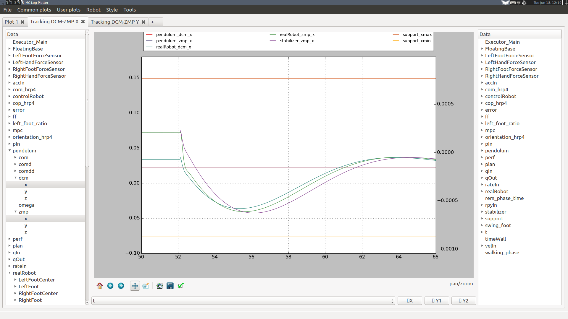
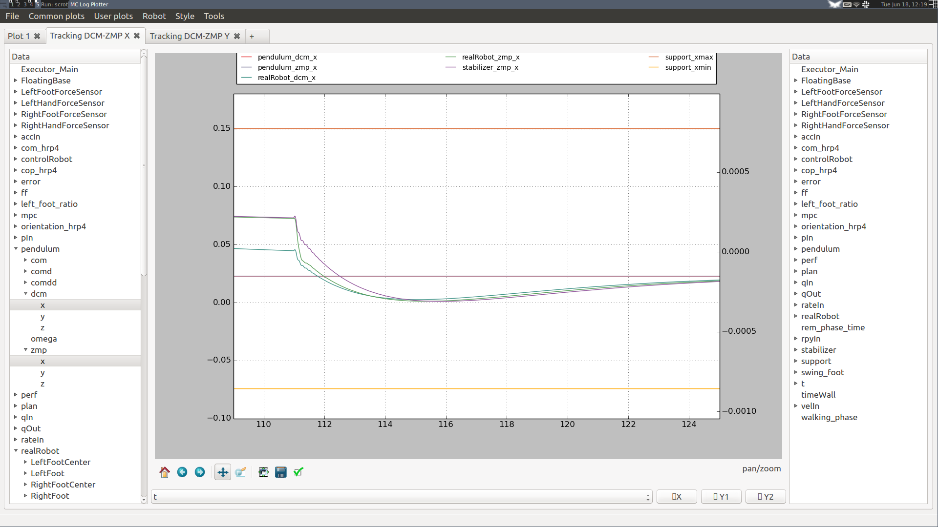
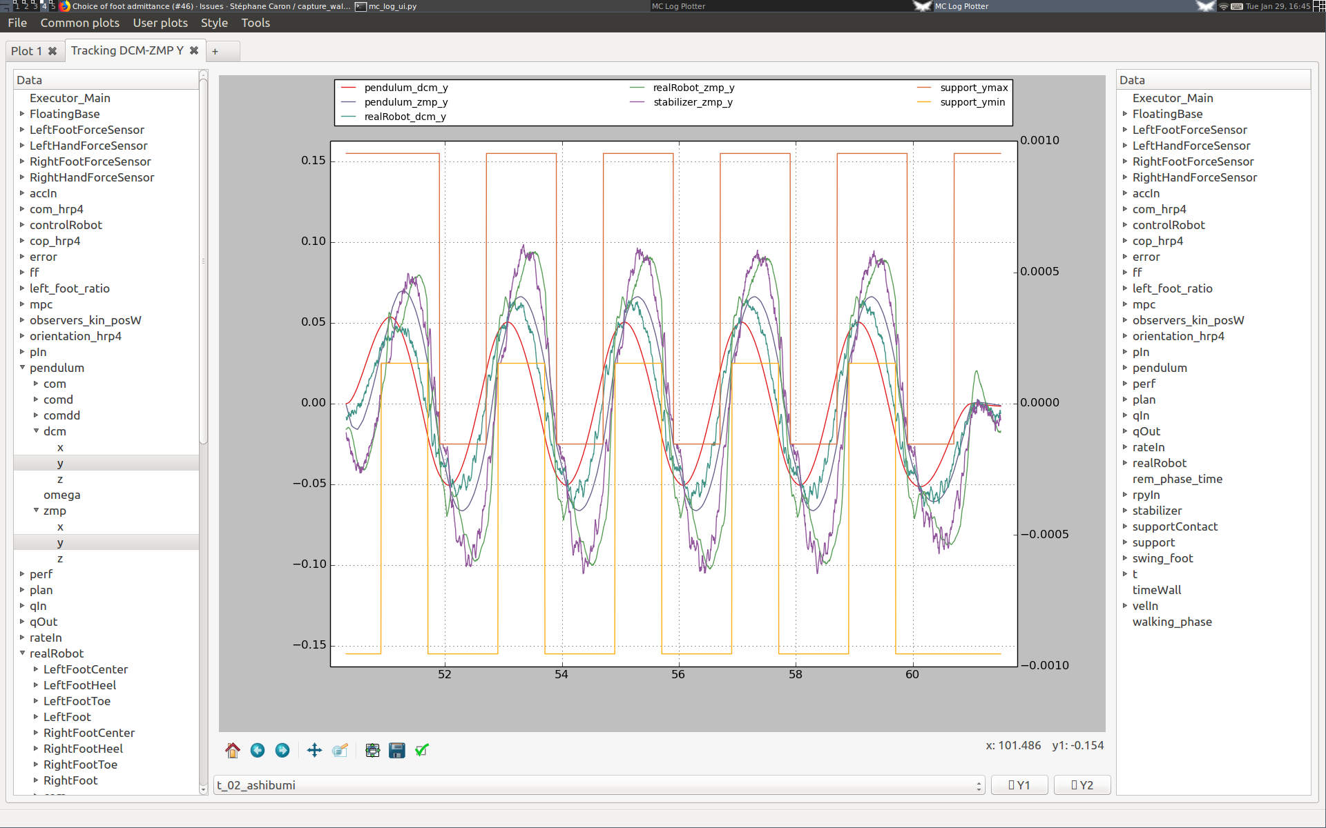
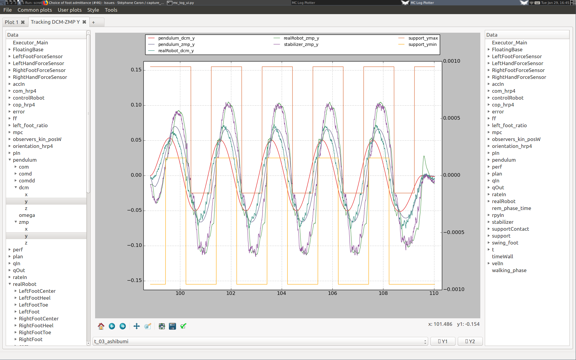
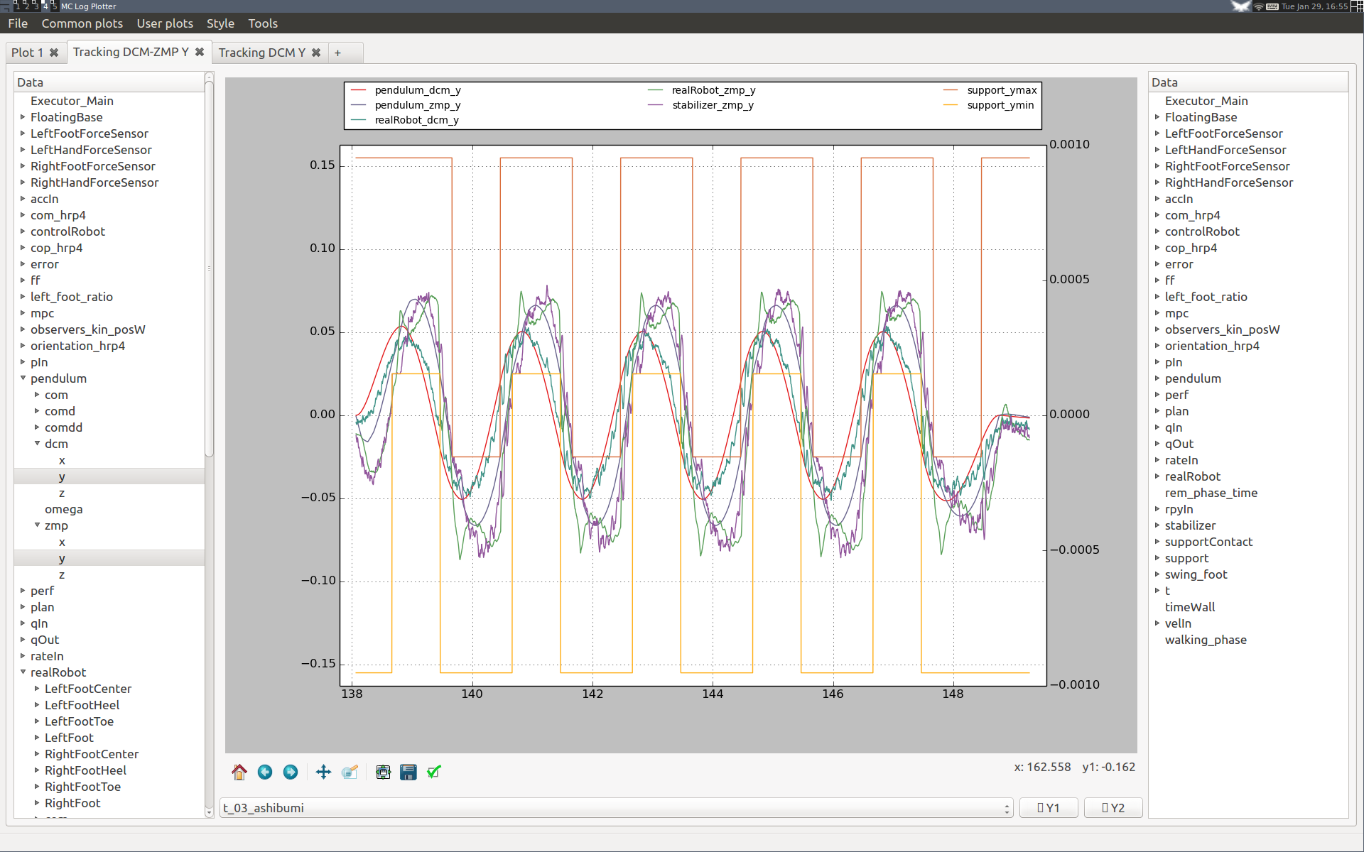
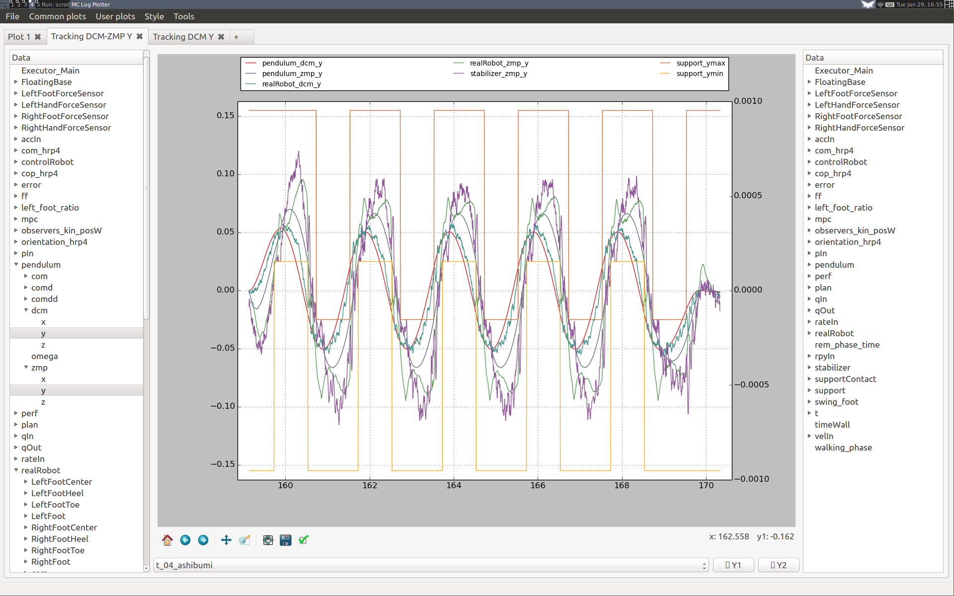
Walking in place evaluates the lateral walking performance and is cheap to reproduce. It corresponds to the ashibumi plan loaded from configuration file (from Japanese 足踏み which means "walking in place"; it has the benefit of beginning with an 'a' so that the plan appears first in the list). Use it to evaluate the effect of different feedback gains on lateral DCM tracking performance over several walking cycles. Here are two examples.
Here are two plots ran on the HRP-4 hardware where we increased ankle CoP admittances from 0.01 to 0.02:
You can see that the force tracking is improved (green realRobot_zmp_y curve is closer to its violet stabilizer_zmp_y target), however DCM tracking degrades, and as a consequence the stabilizer ZMP target shifts further away from the blue reference pendulum_zmp_y from the motion plan. Since our ultimate goal is to control the DCM, the first setting is better than the second one.
Here are two plots ran on the HRP-4 hardware (v1.0 of the controller) where we increased the proportional gain of DCM tracking from 1 to 2:
Although DCM tracking is improved at the beginning of the first step, we can see that the performance is degraded in the long run for the higher DCM gain. After a couple of steps, DCM tracking performance is roughly the same, at the cost of much larger ZMP targets (stabilizer_zmp_y violet curve). We see also in the spikes in measured ZMP (realRobot_zmp_y green curve) that the second setting yields larger touchdown impacts.
Walking forward is the last test in our pipeline. It corresponds to the walk_forward_100cm plan loaded from the configuration file.
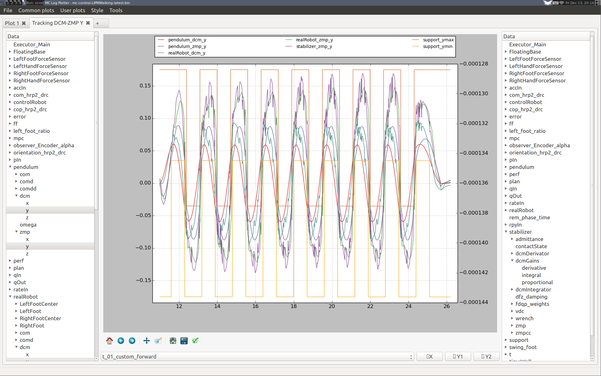
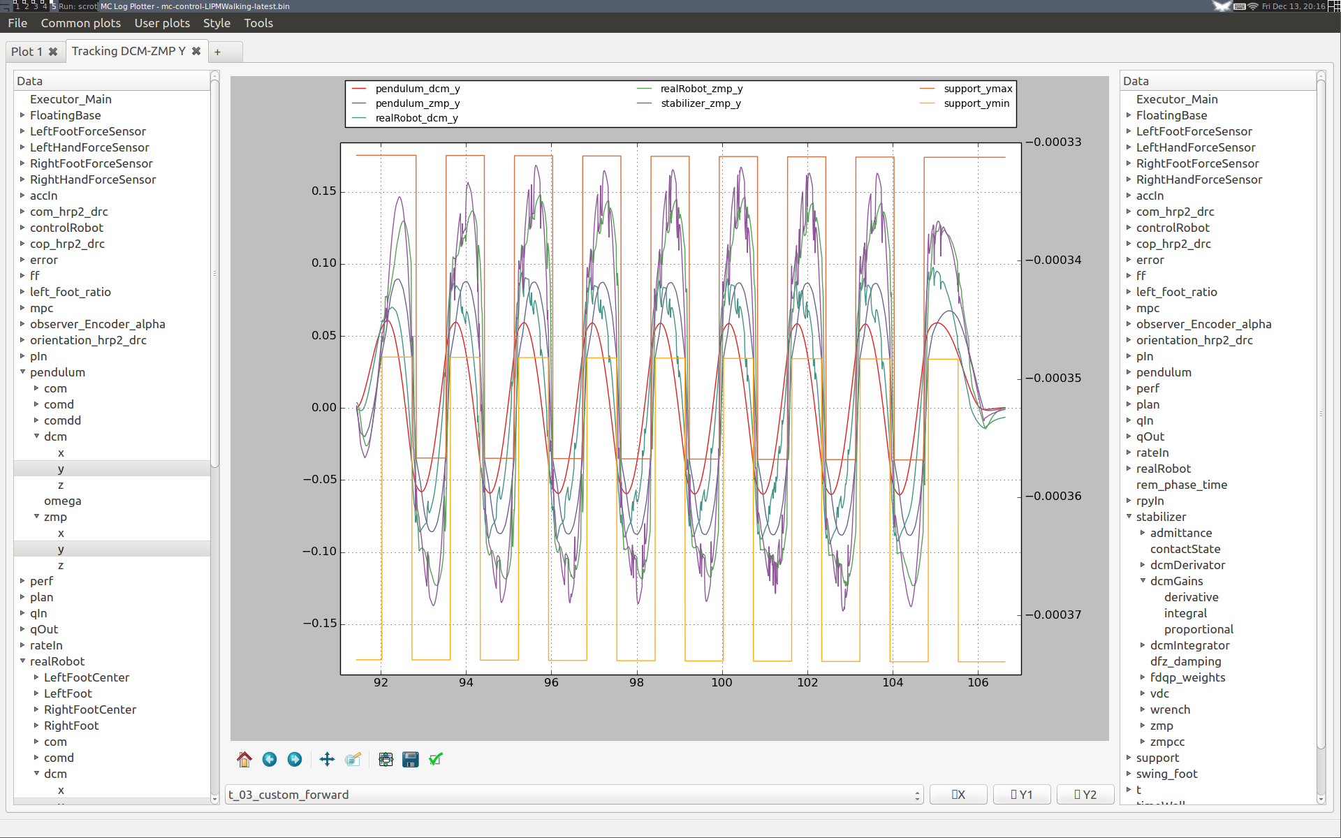
Here are two plots from a Choreonoid simulation of HRP-2Kai (v1.6 of the controller) where we increased the integral gain of DCM tracking from 20 (left) to 42 (right):
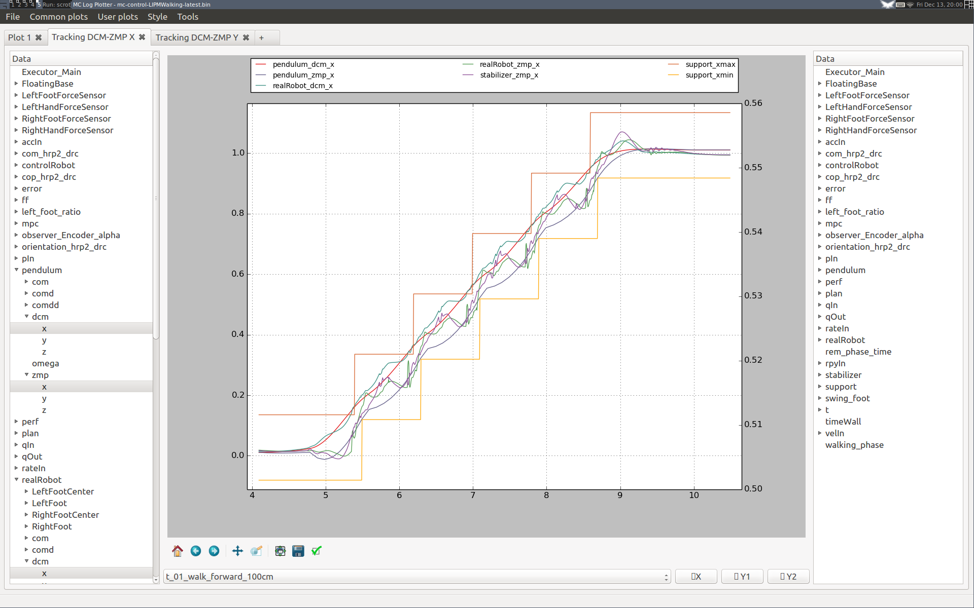
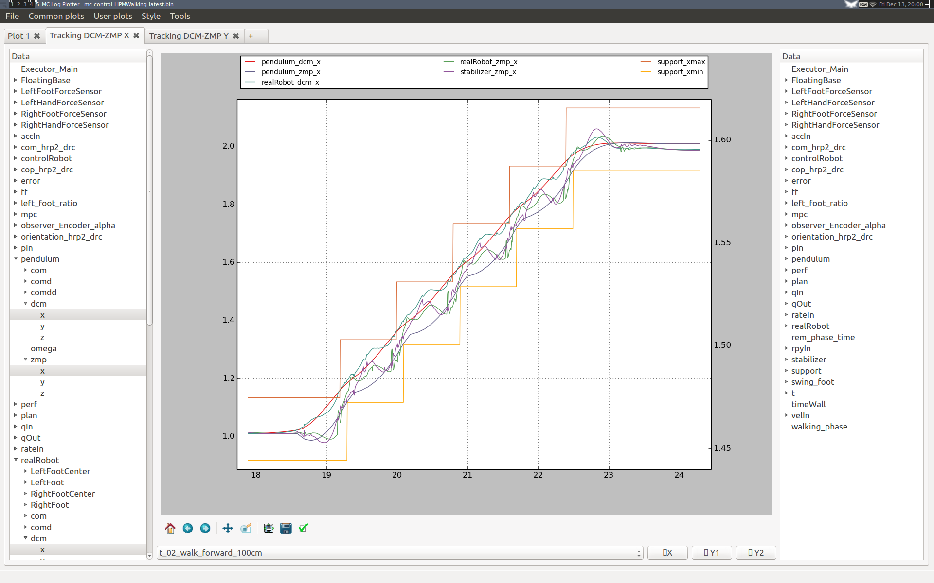
Performance is better on the right-hand side, with both the DCM and ZMP closer to their references. Having the ZMP closer to the ankle frame (which is offset backward from the sole center) is also better to minimize deflection of the flexibility, which in turns reduces our kinematic tracking error and eventually reduces impact.
Here are plots in the lateral direction from the same simulation, walking three meters forward this time:
During the first steps the performance seems slightly degraded, as with a higher integral gain the integrator converges to its steady state behavior faster. We can check this by plotting its error curve:
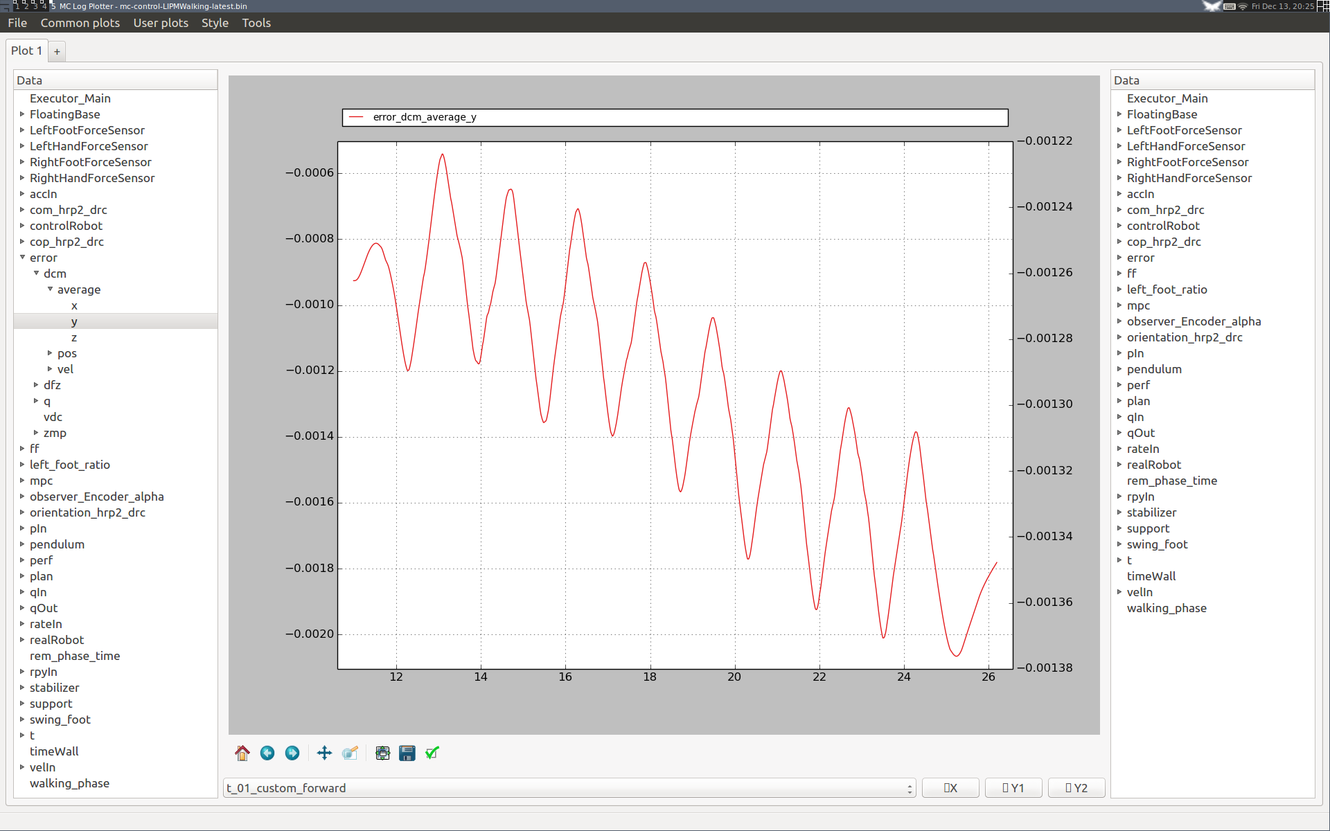
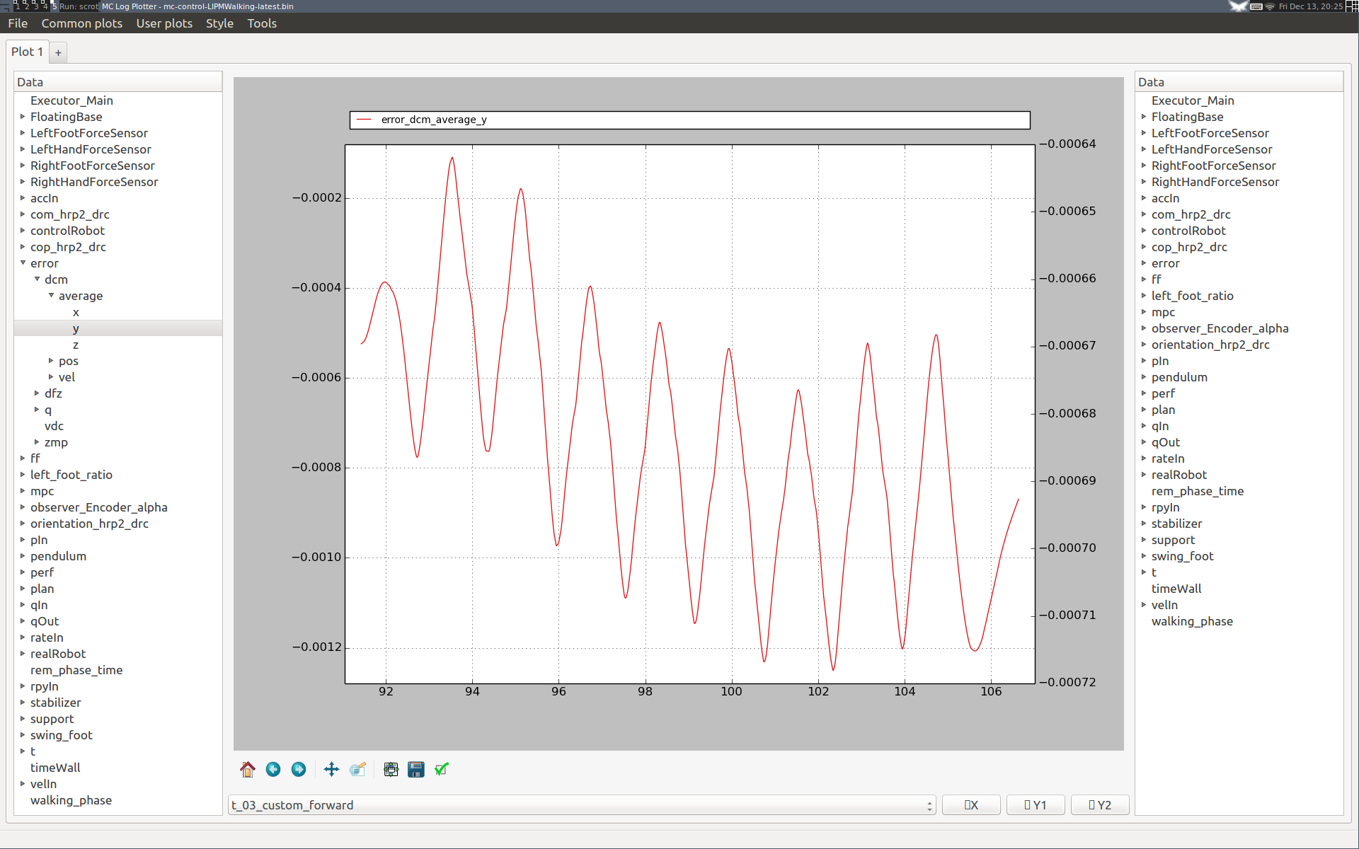
Note that this behavior is general: the integrator "eats up" all our unmodeled effects, so while standing it will converge to a stationary value, and while walking it will drift step by step until reaching repeating oscillations. Overall, our performance loss is only transient and the overall lateral walking performance is not degraded with the higher integral gain. We can conclude that it is thus a better choice for this simulation.
The integrator used to evaluate the average DCM over time is an exponential moving average (EMA) over the last \(T_i\) seconds (see utils::ExponentialMovingAverage). The nominal value for HRP-4 is \(T_i = 10~\text{s}\), which works well in all cases we tested so far.
If you observe slow oscillations during standing after walking, your integrator time constant may be too large. We observed this behavior on HRP-2Kai while experimenting with \(T_i = 15~\text{s}\). In this case, you may want to reduce your integrator time constant or increase your DCM P gain. Smaller time constants reduce the cutoff period of the EMA and thus make the DCM integral term closer to a proportional one. This is not the intended behavior, so if possible you should increase your DCM P gain instead. Look at your average DCM error variations (error_dcm_average log entry) to decide on a course of action.
Additionally, there are two gains for vertical drift control:
| Gain | Effect of increasing |
| frequency | Faster foot height averaging in double support |
| stiffness | Faster foot height drift correction in single support |
These gains are not critical, their purpose is to avoid long-term drift after several steps. Use the Swing foot Z plot to debug them.
 1.8.11
