Multi-contact Stability Support Areas and Volumes for Humanoid Locomotion under Frictional Contacts


Stéphane Caron
LIRMM, CNRS-UM2
Talk at Max Planck Institute
September 19, 2016
https://scaron.info/slides/mpi-2016/
Contact stability
Contact stability of a motion
A motion q(t),τ(t),f(t),C(t) is a solution to the equations of motion:
M(q)¨q+h(q,˙q)=S⊤τ+∑i∈CJ⊤ifiA motion is contact stable if it contains no transition between contact modes, that is, if C(t) is stationary.
Contact stability of a trajectory
A trajectory q(t) in contact state C is (weak) contact stable if it is possible to perform it with no contact switch:
∃{fi∈FCi},M(q)¨q+h(q,˙q)=S⊤τ+∑i∈CJ⊤ifiExample
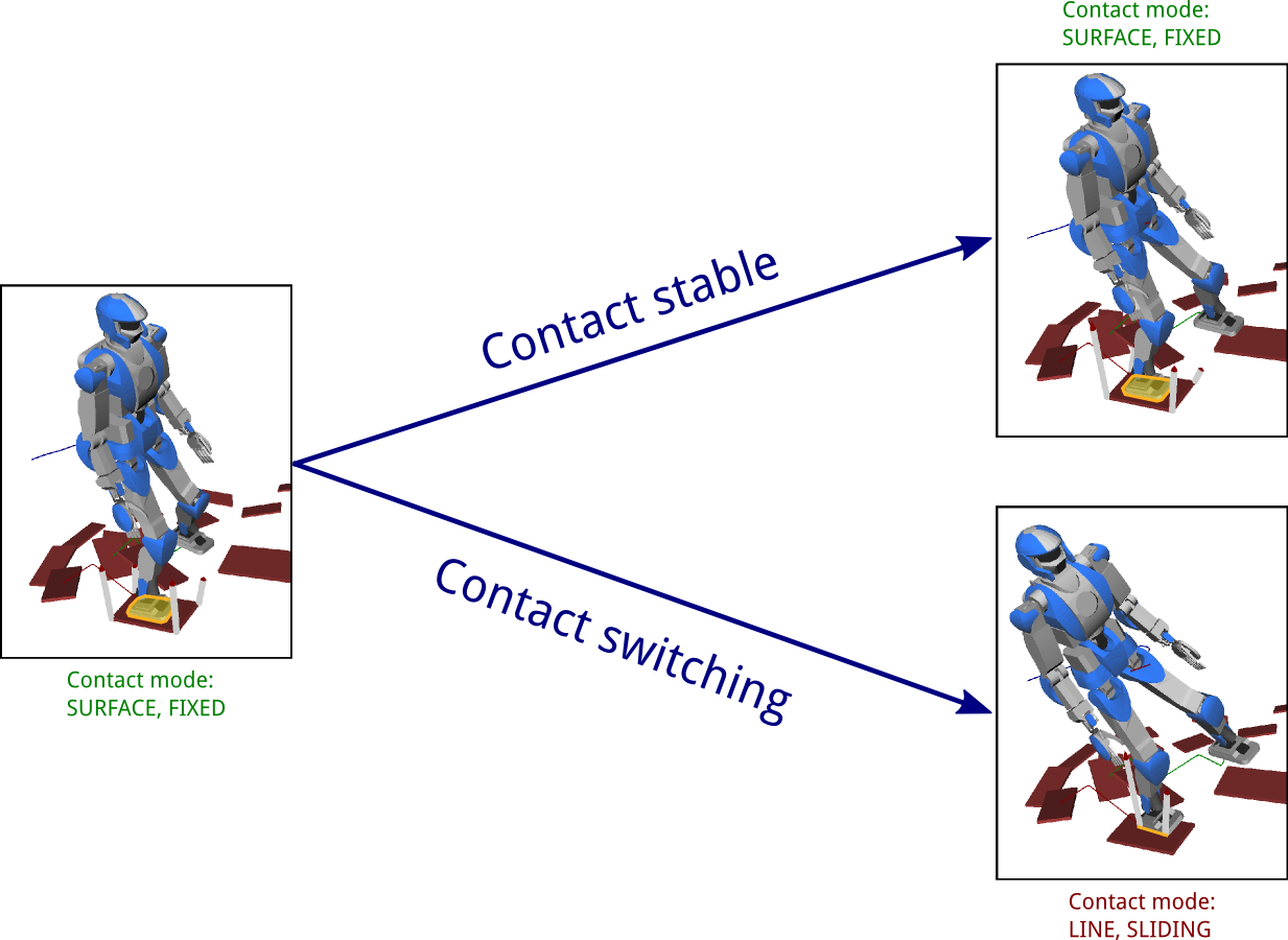
Contact stable
Not contact stable
Zoom on previous example
Contact stable
Not contact stable
Contact modes
Complementarity
Let vi and fi denote the velocity and force on a given DOF i of a rigid body.
When one is equality-constrained, the other is always inequality-constrained:
| vi= | vi≤ |
| fi≤ | fi= |
Contact mode
A contact mode specifies which of vi,fi is equality-constrained for all contact DOFs i.
Example
In the fixed contact mode, all contact velocities are zero Ji˙q=0 and contact forces lie in their friction cones Fifi≤0.
Contact mode graph
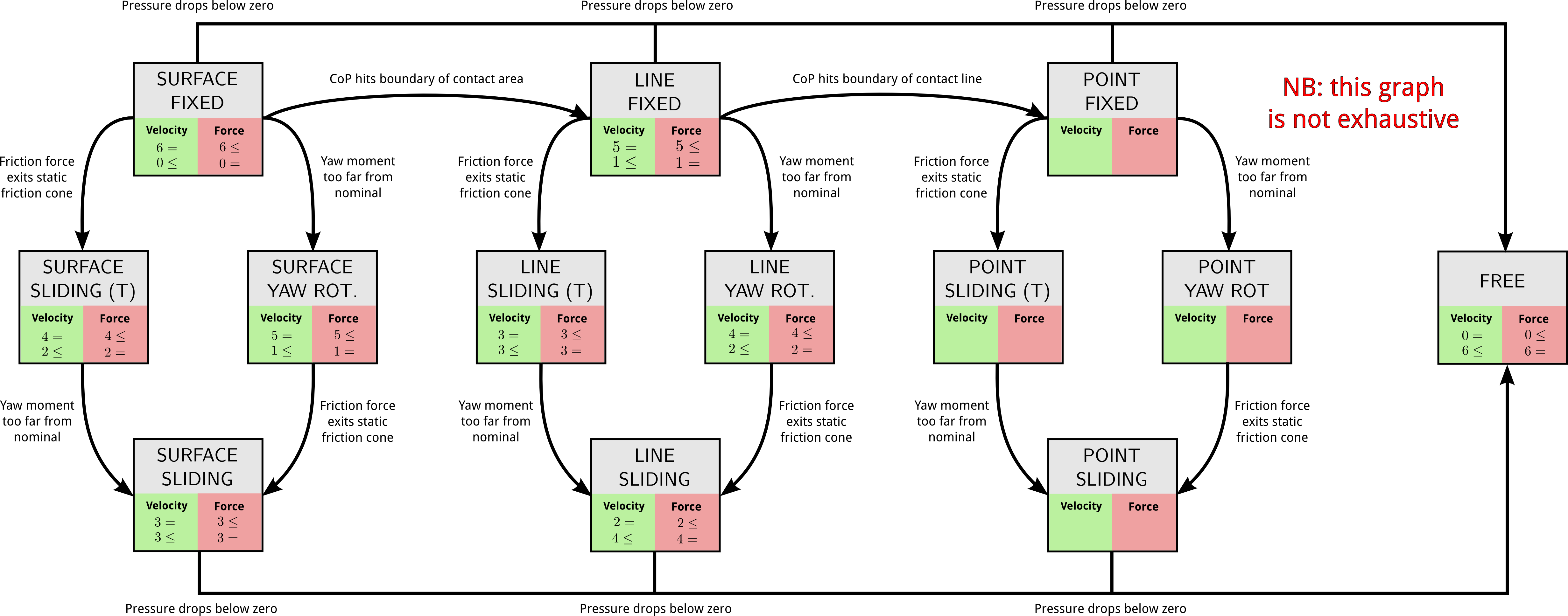
What we currently use
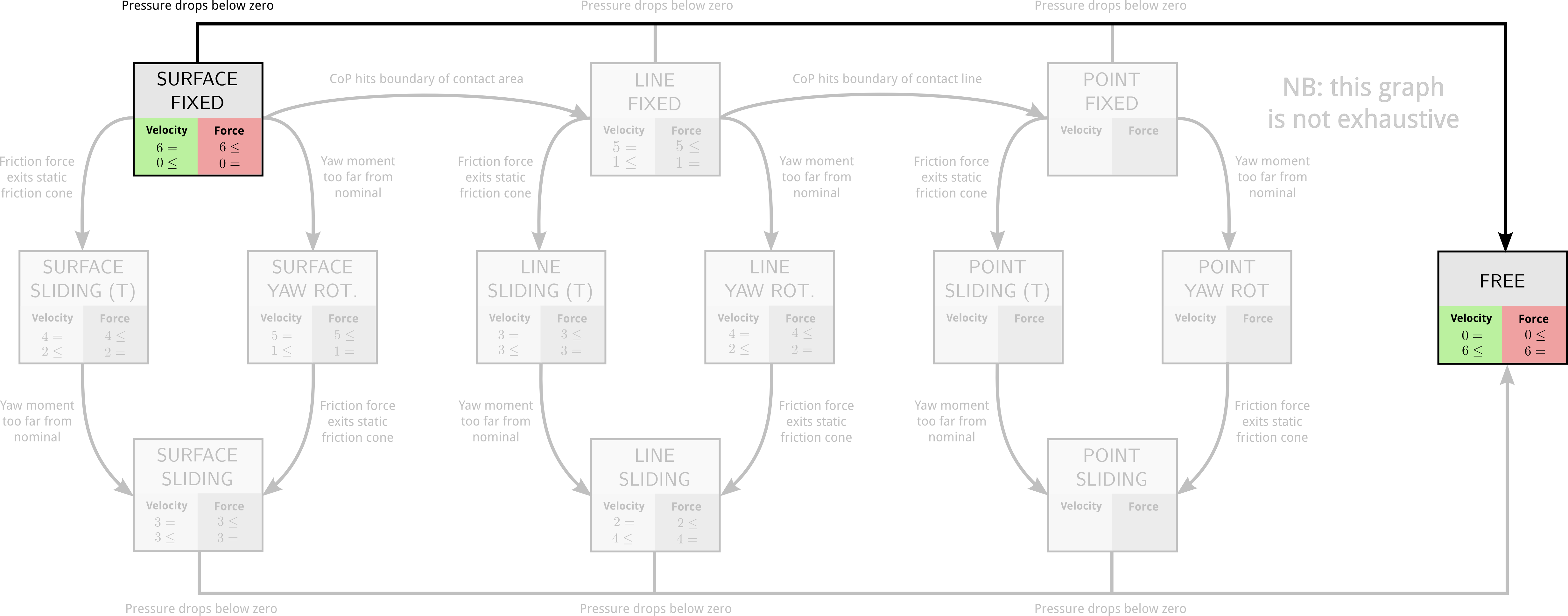
Single contact stability
in the fixed mode
Contact stability
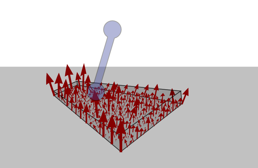
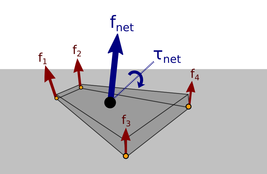
The Contact Wrench Cone characterizes contact stability, that is:
∃{fi∈FCi},M(q)¨q+h(q,˙q)=S⊤τ+4∑i=1J⊤Cifi⇔∃wO∈CWCO,M(q)¨q+h(q,˙q)=S⊤τ+J⊤OwOStructure of the CWC
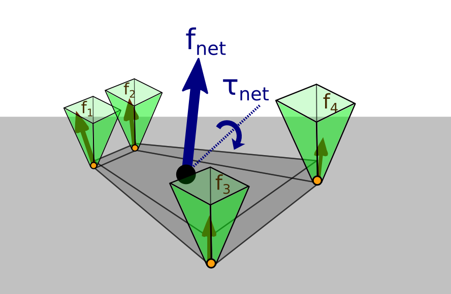
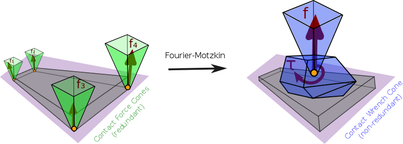
- Friction cone on the net contact force
- Center of pressure condition
- Yaw moment condition
Yaw moment condition
“Torsional friction”
Model found in previous works: |τzO|≤μτfz ... but physically incorrect.
Condition found in the CWC
Taken at the center of pressure C, the correct condition is:
|τzC−τsafe| ≤ μdedgefz- μ: usual static friction coefficient
- dedge: distance to the edge of the contact polygon
- τsafe: function of f and pC (details in (Caron, 2016), p.82)
ZMP support areas
for multi-contact locomotion
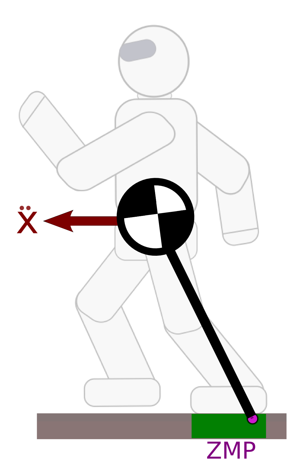
Zero-tilting Moment Point
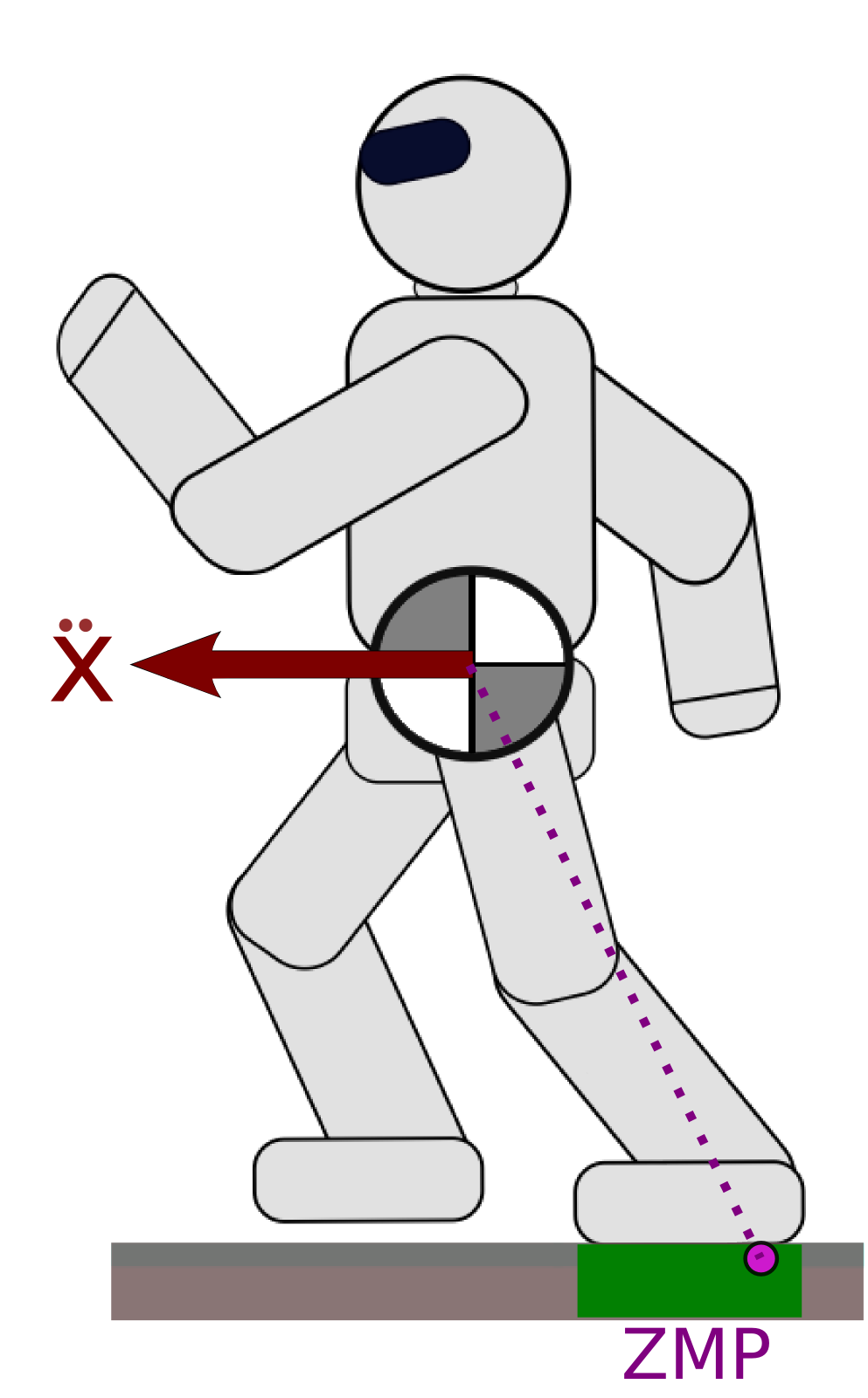
Definition
The ZMP is traditionally defined as the point on the floor where the moment of the contact wrench is parallel to the surface normal (Sardain & Bessonnet, 2004).
Intuition as Center of Pressure
The point at which the robot “applies its weight”.
Contact stability
The ZMP must lie inside the support polygon (convex hull of ground contact points).
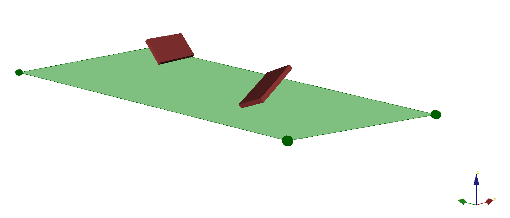
Limitations
- This definition requires a single “floor” surface (no multi-contact)
- The support polygon does not account for frictional limits (slippage, yaw rotations).
ZMP of a Wrench
The ZMP is mathematically defined from a wrench (Sardain & Bessonnet, 2004). The ZMP in the plane Π(O,n) of normal n containing O is the point such that n×τZ=0, that is:
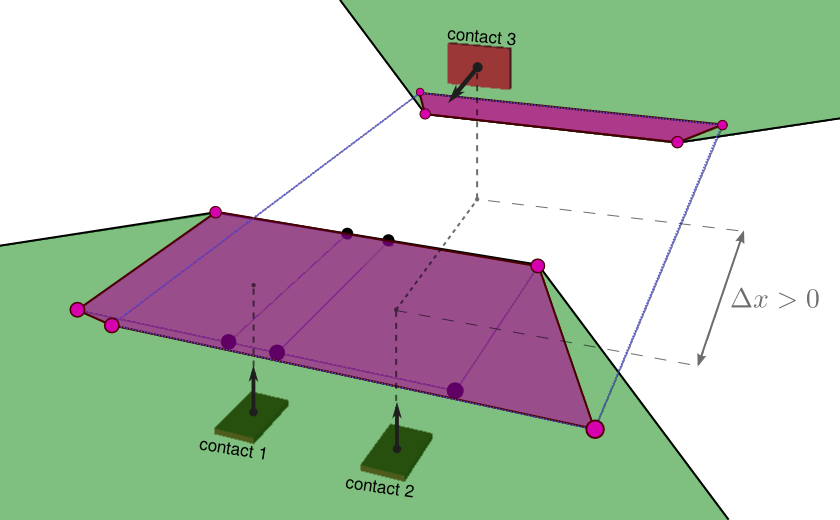
pZ=n×τOn⋅f+pO.We define the full support area S as the image of the CWC by this equation.
Good news
This area can be computed geometrically (Caron et al., 2016):
Bad news
The area is not always a polygon:
Hands on!
Decomposition
The equations of motion consist of two components:
- Newton-Euler equations: “external” interactions between environment and free-floating base:
- Actuated-joint equations: “internal” interactions between motors and joints:
Newton-Euler equations
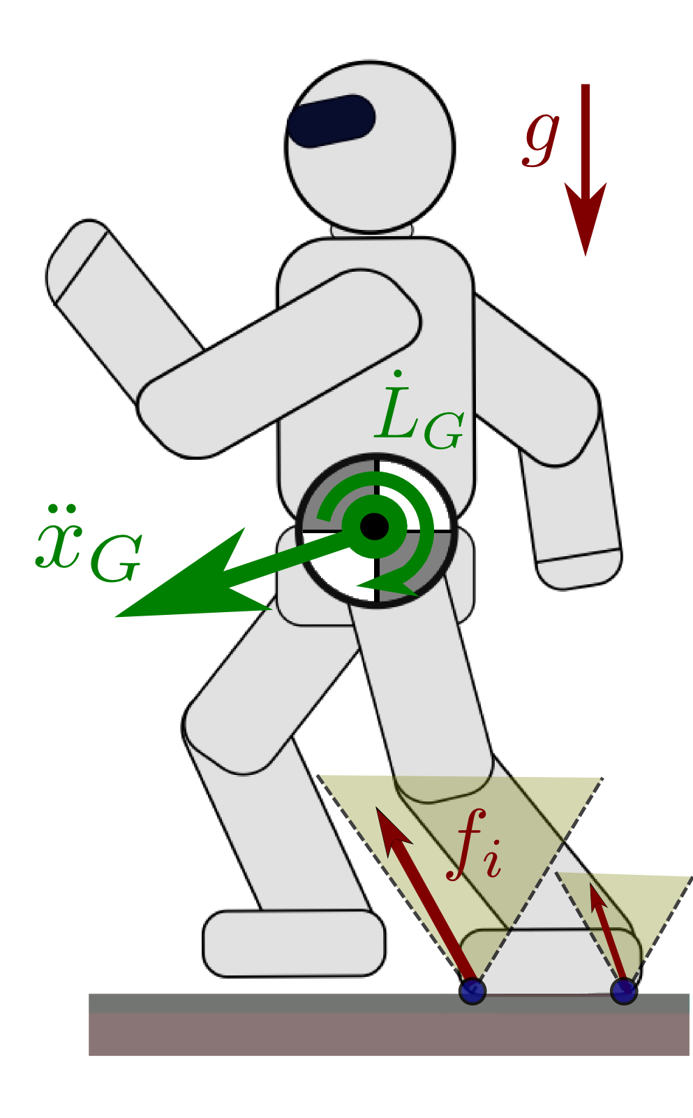
- m and g: total mass and gravity vector
- ¨pG: acceleration of the center of mass (COM)
- ˙LG: rate of change of the angular momentum
- fi: contact force received at contact point Ci
Hierarchical contact stability
First, solve contact stability for the COM and angular momentum trajectory.
Next, joint angles will follow...
Linear Pendulum Mode
The Newton equation can be written equivalently:
¨xG=g+¨zGzG−zZ(xG−xZ)−˙LGxm(zG−zZ)and similarly for ¨yG. The Linear Inverted Pendulum Mode (Kajita et al., 2001) is obtained by constraining:
zG−zZ=h˙LG=0The system dynamics become ¨xG=gh(xZ−xG).
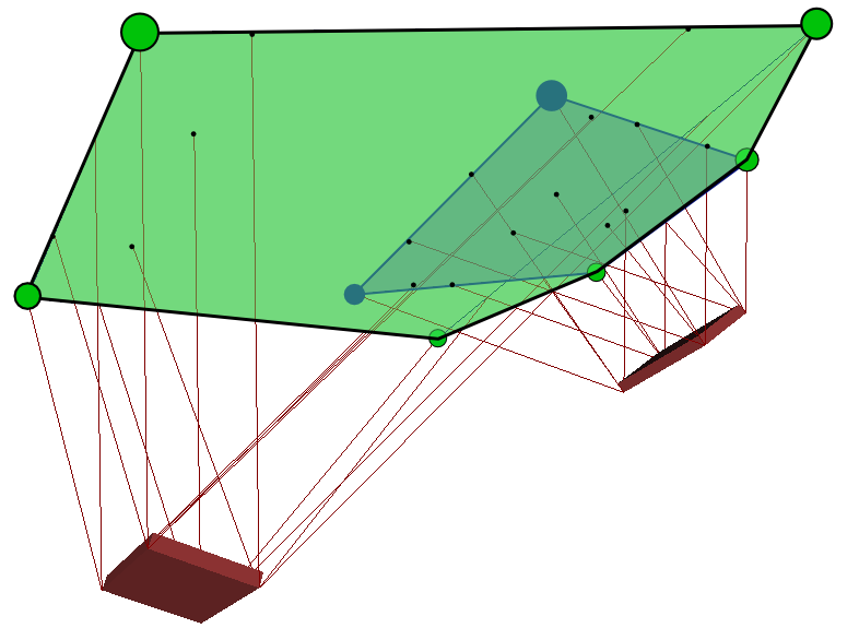
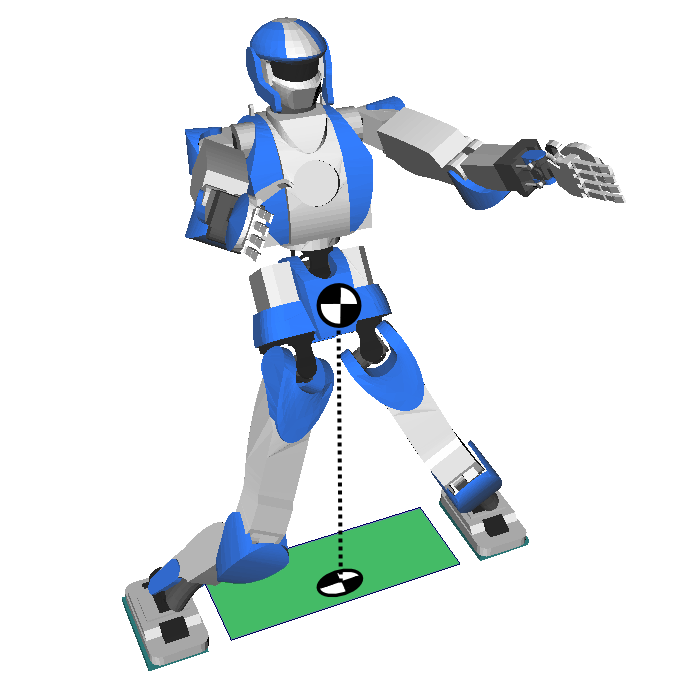
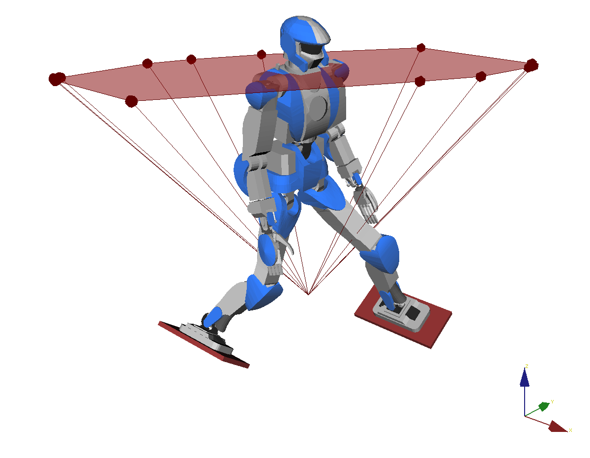
Observation
The support area in the LIPM is smaller than the convex hull of contact points:
Pendular Support Area
The double-description method can be used (Caron et al., 2016) to compute the support area corresponding to the system:
w∈CWCzG−zZ=h˙LG=0We call it the pendular support area.
It is smaller than the full support area and characterizes contact stability in the pendular mode.
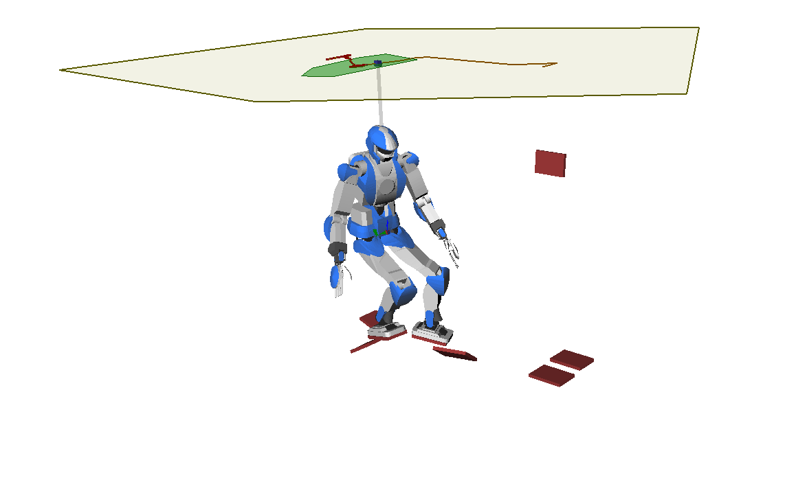
Linear Pendulum Mode
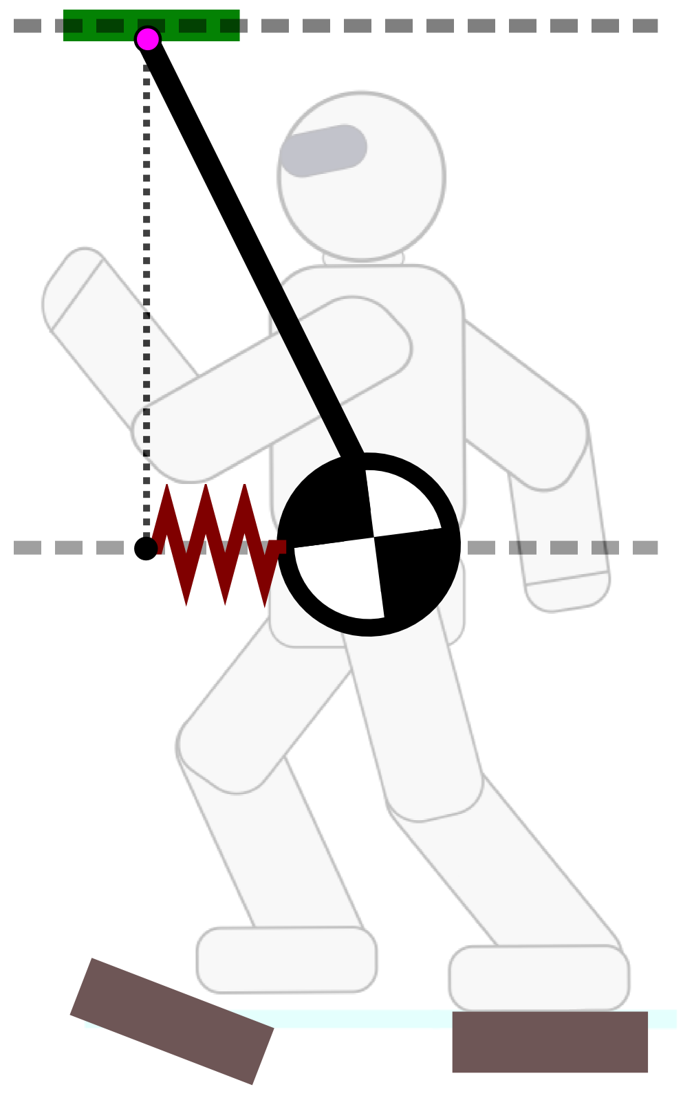
Let us consider the ZMP above the COM:
¨xG = gh(xG−xZ)This is the dynamic equation of a spring.
Attractivity
- LIPM: the ZMP is a repellor of the COM
- LPM: the ZMP is a marginal attractor of the COM
Control law where the robot is driven from above.
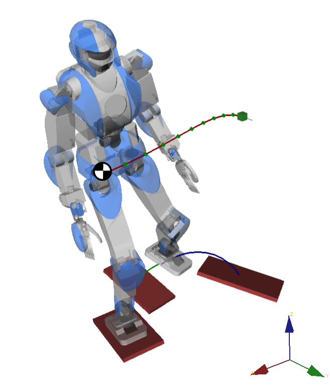
Demo 2
Beyond Good and ZMP
a multi-contact walking pattern generator
Cone of 3D COM Accelerations
Beyond ZMP
Removes the planar COM constraint.
Calculation
Algorithm to compute it as convex hull of 2D dual points, fast and numerically robust (Caron & Kheddar, submitted).
Predictive control
Consider the linear control problem:
x(k+1)=Ax(k)+Bu(k)- x(k): COM state (position and velocity) at preview time kΔT
- u(k): COM acceleration at preview time kΔT
Optimization problem
Predictive control achieves a task over a preview horizon:
min{u(k)} ∥x(N)−xgoal∥2+ϵ∑k∥u(k)∥2s.t. ∀k, u(k)∈C(x(k))where C(x(k)) is the COM acceleration cone at time step k. This constraint is linear-quadratic due to its dependency on x(k).
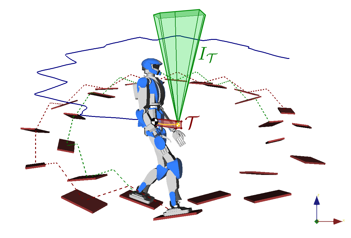
Linearizing the MPC problem
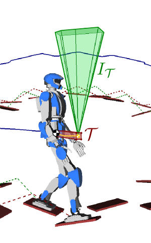
Idea
Bound the preview COM trajectory in a tube T, then compute the intersection:
IT=⋂pG∈TC(pG)Conservative contact-stability criterion.
Inequality constraints
Decouples u(k)∈C(x(k)) into:
CTu(k)≤0PTx(k)≤0Demo 3
Sweets for later
When to make a step?
Problem: fixed step timings do not work any more in multi-contact (now depends on terrain topology).
Time-Optimal Path Parameterization
Given a path q(s) and dynamic constraints, TOPP finds a retiming q(t) satisfying all constraints and with minimum duration.
Integration with the MPC
Continuous interpolation/retiming loop running at 20-30 Hz thanks to a new TOPP-Polygon algorithm.
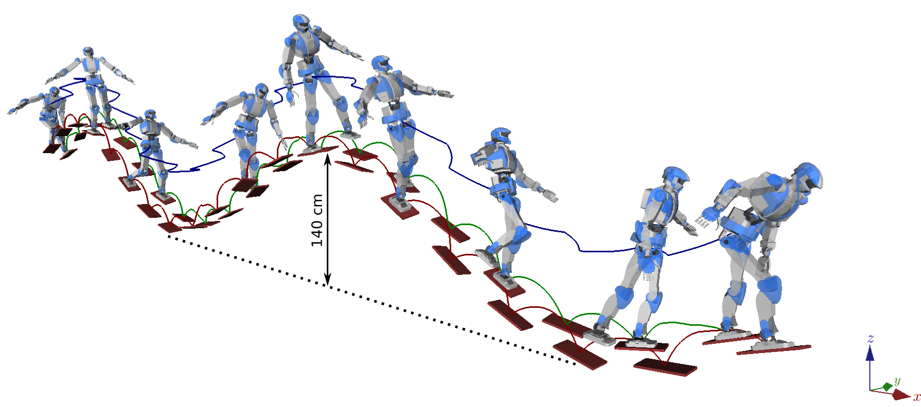
Demo 4
Wrapping remarks
Single contact stability
Analytical formula of the CWC: friction cone, COP area, yaw moment.
ZMP support areas
Applicable to general multi-contact locomotion, but COM planar constraint.
3D COM acceleration cones
Generalizes the latter. Computed fast enough for the control loop.
Multi-contact Walking Pattern Generator
Use a QCQP solver, or... linearize inequality constraints.
Thank you for your attention.